FC2250-UM-251-9370 7-35
7. DISASSEMBLY AND ADJUSTMENT
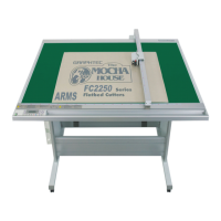
7.4 .3 Adjusting the Y Motor Belt Tension
(1) After loosening the two M3 binding head screws indicated by the (A) arrows in the gure below, attach
a string around the Y motor and pull the Y motor with a 5 kgf push-pull gauge to the point where FY1
equals 2.0 kgf - 0.2, then tighten the two M3 binding head screws.
FY1 = 2.0 kgf - 0.2
(5 kgf push-pull gauge)
(A)
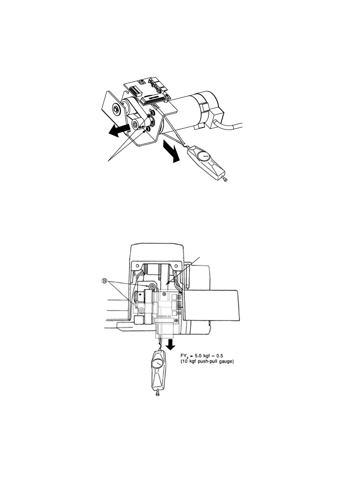
7.4.4 Adjusting the Y Drive Belt Tension
(1) After loosening the two M4 binding head screws indicated by the (B) arrows in the gure below, attach
a string around the Y motor and pull the Y motor assembly with a 10 kgf push-pull gauge to the point
where FY2 equals 5.0 kgf - 0.5, then tighten the two M4 binding head screws.
Synchro belt