FC2250-UM-251-9370 8-19
8. ELECTRICAL ADJUSTMENTS
8.12 Adjusting the Distance and the Perpendicularity Accuracy
This adjustment will set the distance and the perpendicularity accuracy.
If you replace the main board or clear the Non-Volatile RAM, use the following procedure to input the
recorded adjustment values.
How to adjust the distance accuracy
(1) Mount a ceramic pen (0.2 mm tip size) in the No.1 pen holder.
(2) Set the plotting conditions to the following settings with the normal mode:
Force: 12, Speed: 40, Quality: 1, Tool: Pen
(3) Load a sheet of A1 or A2 size paper in the plotter.
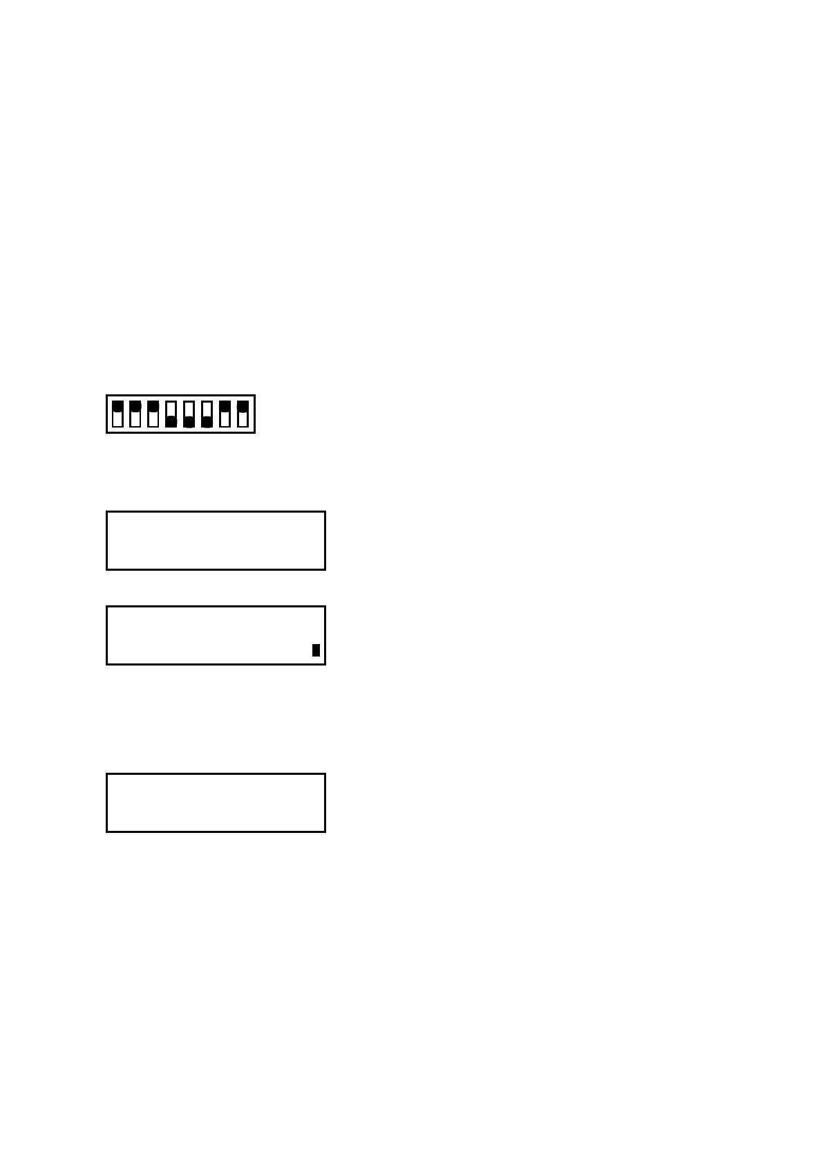
(4) Set the DIP switch to the adjustment mode as shown below.
Electrical Adjustments
Set bits 4, 5, and 6 to OFF
12345678
ON
OFF
(5) Turn on the power to the plotter.
(6) Press the [NEXT] key until the following menu is displayed.
DIST. ADJ. (0.01mm)
PRESS ENTER KEY !!
(7) Press the [Enter] key to display the menu shown below.
SEl SIZE 300x300
200x200 500x700
(8) Press the [F4] key to select the 500x700 mm adjustment pattern.
(Press the [F2] key to select the 300x300 mm adjustment pattern when you are adjusting the FC2250-
60.)
(9) Press the [Enter] key to display the menu shown below.
<ORIGINAL CLEAR>
<ADJ.DRAW INPUT>
F1 key (ORIGINAL) :Draw the test pattern without distance adjustment.
F2 key (ADJ. DRAW) :Draw the test pattern with distance adjustment.
F3 key (CLEAR) :Clear the distance adjustment value.
F4 key (INPUT) :Move to the distance adjustment value setting menu.