FC2250-UM-251-9370 8-22
8. ELECTRICAL ADJUSTMENTS
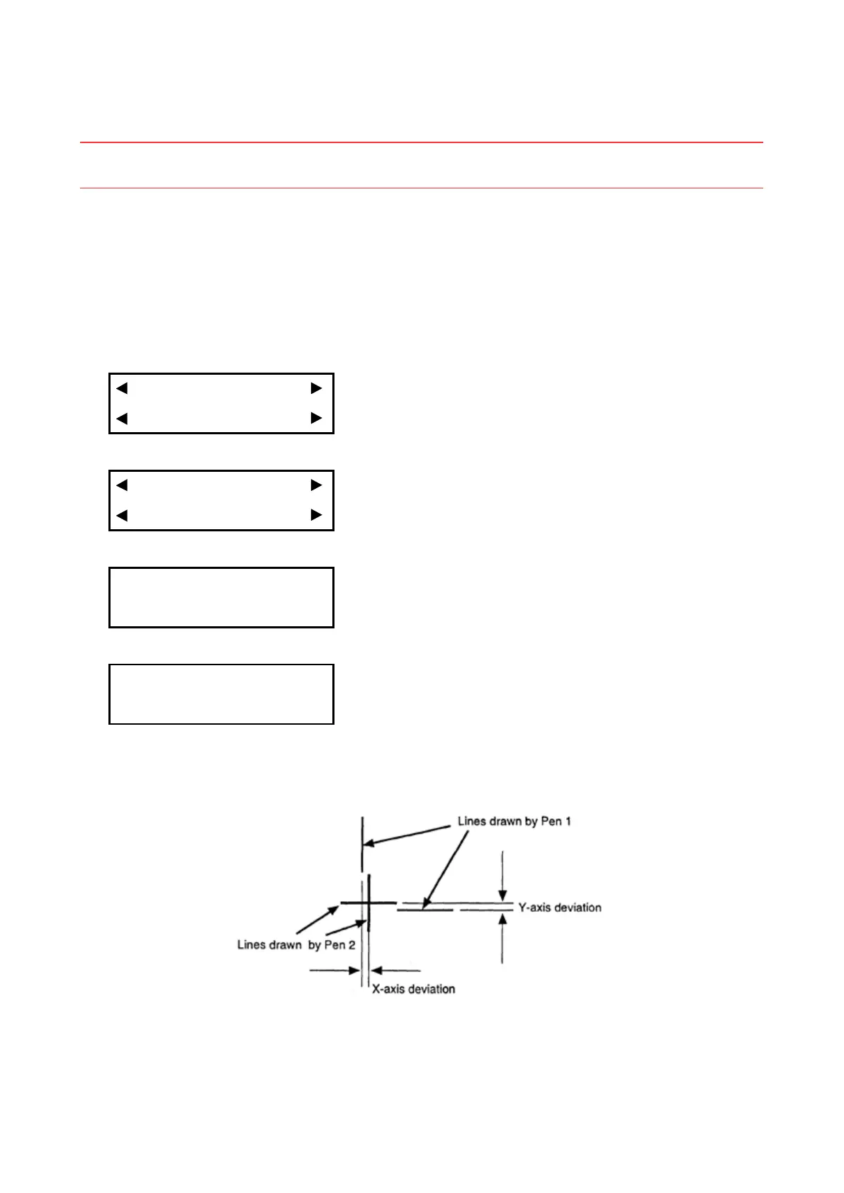
8.13 Adjusting the Pen Interval
This enables adjustment of the distance between the origins for Pen 1 and Pen 2.
Note: Pens are used to draw lines for this adjustment. As described below, mount pens in the Pen 1
and Pen 2 positions, then specify their conditions.
Procedure
(1) Load a medium that is suitable for plotting.
(2) Mount pens in the Pen 1 and Pen 2 positions.
(3) Set the plotting conditions to the following settings with the normal mode:
Force: 12, Speed: 40, Quality: 1, Tool: Pen
(4) Press the [PAUSE] key to select PAUSE mode.
(5) Press the [NEXT] key repeatedly until the following menu is displayed.
I/F FUNCTION
TOOL COND AREA OPT
(6) Press the [F2] key (TOOL COND) to display the menu shown below.
THICK CUT LINE
TOOL No. ADJ.T POS
(7) Press the [F4] key (ADJ.T POS) to display the menu shown below.
TOOL WIDTH ADJ.
X= 0.0mm Y= 0.0mm
(8) Press the [TEST] key to display the menu shown below.
SELECT PLOT POINT
PRESS ENTER KEY!
Use the position keys to move the pen carriage (the tip of the tool selected by the current setting) to the
position where you want to draw the test pattern. Press the [ENTER] key. The plotter will start drawing
the following test pattern.