FC2250-UM-251-9370 1-7
1. INTRODUCTION
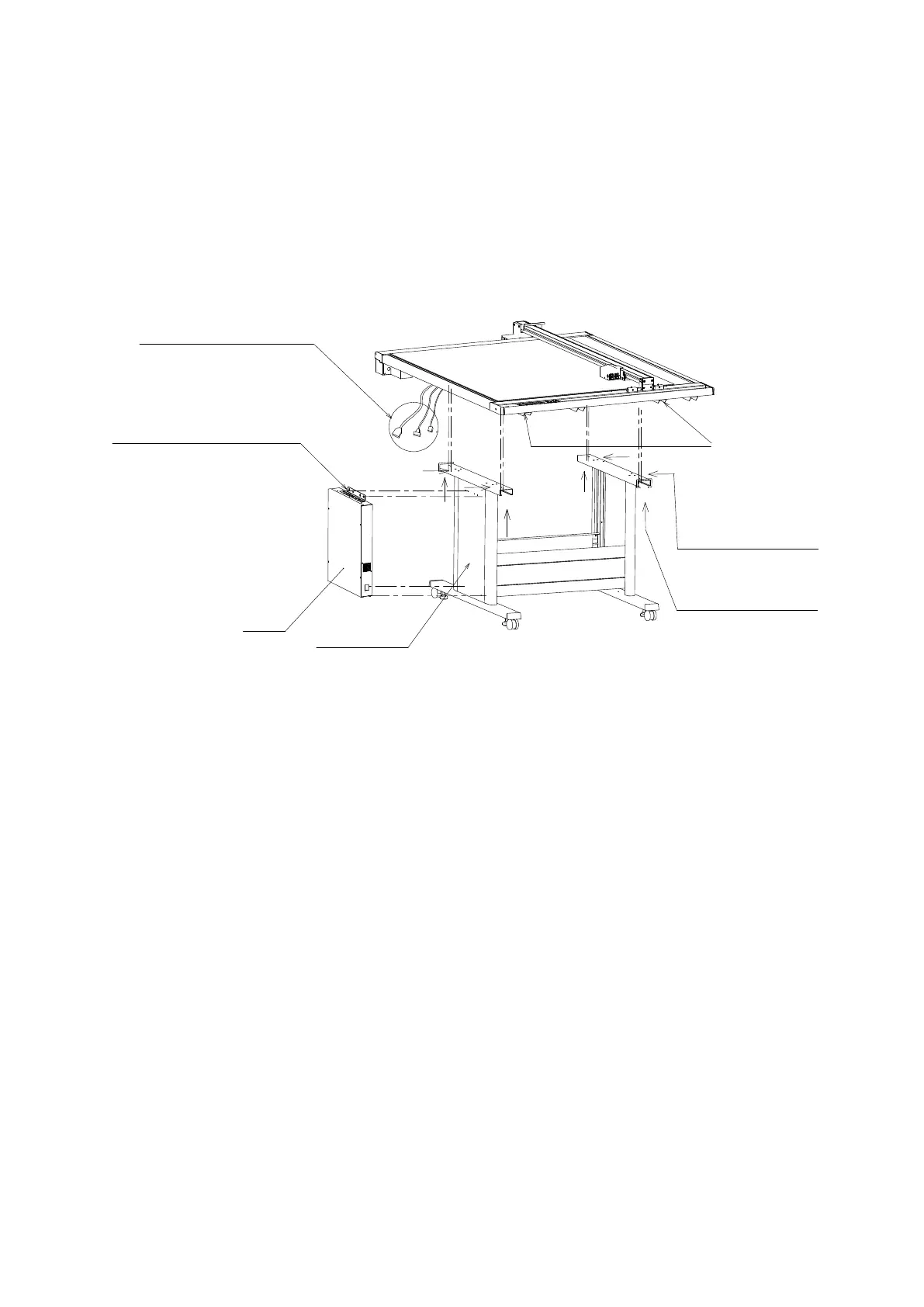
1.6 Mounting Procedure
Screws provided for assembly
1. M4 x 8 bind-head screws: 8 for FC2250-60, 4 for FC2250-120/180
2. M3 x 8 bind-head screws: 6
Procedure
(1) When mounting the FC2250 unit onto the stand, make sure that it is correctly oriented. The three cables
protruding from the FC2250 should be at the control box side.
(2) Position the FC2250 so that the underside of the frame is mounted on top of the stand.
After the FC2250 unit has been mounted on the
stand, insert the cables protruding from the underside
into the control panel box.
The control panel box is affixed to the side of the stand with
four M3 x 8 screws at the top and two at the bottom.
To facilitate the mounting of the control box on the stand,
insert the screws into the stand side first, leaving a gap,
and then mount the control box.
Control box
Note:
The surface with the M3 tapping screws
is the surface on which the control box is mounted.
FC2250 frame
FC2250-60:
FC2250-60:
FC2250-120/180:
FC2250-120/180:
Two L-shaped brackets
Gas Spring Bace Bracket
Screw in the M4 x 8 screws into the
brackets from the underside.
There are two screws each at four
locations, for a total of eight screws.
Screw in the M4 x 8 screws into the
brackets from the side.
There are two screws each at two
locations, for a total of four screws.