FC2250-UM-251-9370 8-20
8. ELECTRICAL ADJUSTMENTS
(10) Press the [F1] key to start the test. The plotter immediately plots the test pattern, and the following menu
appears.
DIST. ADJ. (0.01mm)
X =+10 Y =-10
Y=700 (300) mm
X=500 (300) mm
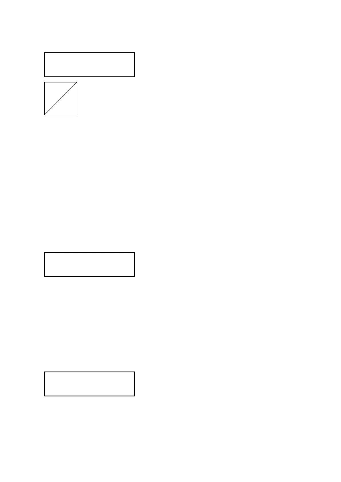
(11) Remove the paper and measure the X-axis distance, Y-axis distance and the diagonal distance. If you
have replaced the main board only, use the recorded values.
(12) Input the axis adjustment values using the F1 to F4 keys.
Press the [F1] or [F2] key to change the X-axis adjustment value.
Press the [F3] or [F4] key to change the Y-axis adjustment value.
The formula of the input value is as follows (FC2250-120/180):
Input value for X-axis = (500 mm - measured distance) x 10
Input value for Y-axis = (700 mm - measured distance) x 10
For example:
If you measured 499.7 mm for the X-axis, input 30 for the adjustment value.
Press the [F1] key to select the +0.1-mm step unit.
(13) Press the ENTER key to display the menu shown below.
+0.1 X-Y LENG -0.1
+0.01 L=860.23 -0.01
[F1] key (+0.1) :Increase the diagonal distance value in 0.1-mm steps.
[F2] key (+0.01) :Increase the diagonal distance value in 0.01-mm steps.
[F3] key (-0.1) :Decrease the diagonal distance value in 0.1-mm steps.
[F4] key (-0.01) :Decrease the diagonal distance value in 0.01-mm steps.
(14) Input the diagonal adjustment values using the [F1] to [F4] keys.
The displayed L value is the diagonal distance.
IfthemeasuredvalueiswithinthedisplayedLvalueofthespecicationrange(±0.1mm)orifyouhave
input the recorded value, press the [ENTER] key to store the setting.
(15) The following menu appears.
<ORIGINAL CLEAR>
<ADJ.DRAW INPUT>