120
Program description - Control adjust | Helicopter models
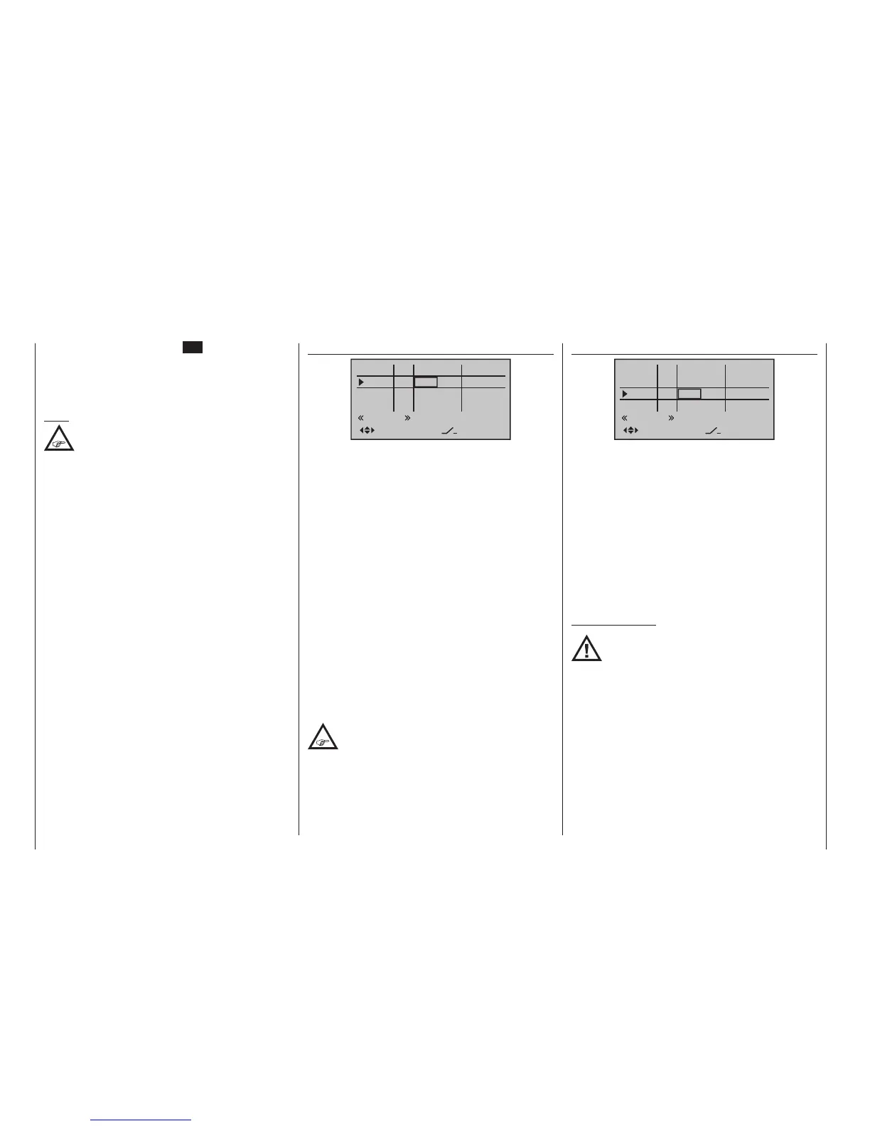
“Gyro”
0%
0%
0%
–––
0%
Gyro
In8
–––
–––
–––
GL
GL
GL
GL
normal
fr
fr
fr
SEL
fr
In5
offset
Thro
typ
Most of the latest gyro systems not only feature infi-
nitely variable proportional gyro gain setting, but also
offer a choice of two separate types of gain mode on
the transmitter.
If the gyro in use also has this feature then this menu
option provides the opportunity to specify both a “nor-
mal” gyro effect as well as a “heading-lock mode” in
the “Offset” column within a range of ±125 %. Such a
specification can include a certain effect to fly normal,
slow flights with maximum stability or the reduction of
the gyro effect for fast circuit flights and aerobatics.
To proceed as described above, use flight phase
switching to enter different settings on the “Gyro” line.
Important notice:
The value of this option is identical to the
offset value set in the “Gyro offset” option
of the »Helicopter mixer« menu, page
193. For this reason, any changes made always
affect the other menu directly, and vice versa.
Beginning with these preset – static – flight phase-
specific settings, a transmitter control assigned to the
“Gyro” line, for example one of the middle console
sliders, can be used to vary the gyro effect around the
respective “offset point”. The centre point of the control
corresponds to the setting specified by the offset. If the
transmitter control is moved from this centre point in
the direction of full travel, gyro gain increases propor-
tionally;
“Thro(ttle)”
0%
0%
0%
–––
0%
Gyro
In8
–––
–––
–––
GL
GL
GL
GL
normal
fr
fr
fr
fr
SEL
In5
offset
Thro
typ
In principle, the helicopter program also permits the
individual inputs to be assigned to any existing trans-
mitter control (proportional controls and switches).
However, please note here that some of the inputs
available on this menu are already assigned to helicop-
ter-specific functions, and therefore cannot be re-as-
signed in this way.
Nevertheless, the receiver layout on page 67 indi-
cates that the throttle servo or the speed controller of
an electrically-powered helicopter must be connected
to receiver output “6”, since control channel “6” is
reserved for motor power regulation.
Unlike a fixed-wing model aircraft, the throttle servo or
speed controller is not directly controlled by the stick or
other transmitter control but rather by a complex mixer
system, see »Helicopter mixer« menu beginning
page 184. Furthermore, the “Throttle limit function”
described on the next page also influences this mixer
system.
Assigning a transmitter control or switch on the “Throt-
tle” line, or to its supplementary control signal, would
unnecessarily “confuse” this complex mixer system.
For this reason the “Throttle” input MUST
be left “free”.
Another brief tap on the centre SET key of the right
four-way button will complete the entry.
A simultaneous tap on the or keys of the right
four-way button (CLEAR) will reset the changed pa-
rameter displayed in inverse video back to 0.0s.
Note:
Suggestions for the structure of temporal
sequences, see “Controlling timed sequences”
on page 310.

 Loading...


