177
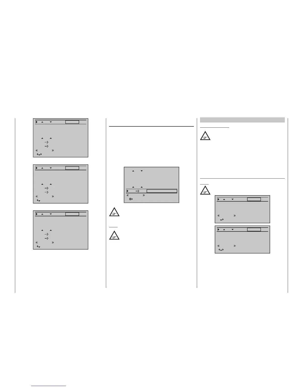
Program description - Wing mixers
FL
0%
0%
fl.pos
EL FL 0%0%
0%
AILE2
normal
Diff.
0%
Ail-tr
AI
+100%
+100%
EL FL Off.
0%
–––
… are supplemented by the columns “FLAP” …
FL
0%
+100%
fl.pos
EL FL 0%0%
+100%
FLAP
normal
Diff.
0%
Ail-tr
AI
0%
0%
EL FL Off.
0%
–––
… and “FLAP2”:
FL
0%
+100%
fl.pos
EL FL 0%0%
+100%
FLAP2
normal
Diff.
0%
Ail-tr
AI
0%
0%
EL FL Off.
0%
–––
Delta/ying wing type models with more than two
wing aps
If you have selected the “Delta/fl“ tail type and selected
the number of wing flaps in the “Aile/flaps” line on the
»Model type« menu (following the instructions given
in that section on page 99), then the two ailerons
will normally not move when you move the elevator
stick – and the same will be true for the inner flaps (FL)
and FL2 (if present). The reason for this is the default
mixer ratio of 0% for all wing flaps, set for the “EL
FL” mixer that is to be found on the multi-flap menu:
FL
0%
0%
fl.pos
EL FL 0%0%
0%
AILE
normal
Diff.
0%
Ail-tr
AI
+100%
+100%
Accordingly, you must first specify your desired
elevator control on the “EL FL” line. Take
care to ensure that up/down activation occurs
in the right sequence.
Note:
The “Brake settings” sub-menu (see page
177) is also suitable for setting up the
buttery (crow) function with delta and ying
wing models. In ne-tuning the deection of the ap
pairs AIL, FL and (if present) AIL2 and/or FL2,
however, ensure that the moments created by one
pair of aps compensate the moments created by the
other pair of aps in each case. For example: the “up”
effect of ailerons when deected up should be
compensated by a “down” effect from aps when they
are lowered.
Multi-ap menu
Important notice:
Depending on the ap pairs specied in the
»Model type« menu, page 98, this menu
will present the column “AILE2” and/or the
columns “FLAP” and “FLAP2” in addition to the
“AILE” column. Since both the columns “AILE” and
“AILE2” and the columns “FLAP” and “FLAP2” are
identical except for the label shown at the bottom
right, further display of the columns “AILE2” and
“FLAP2” is avoided below for reasons of saving
space.
AI
Flaps)
Note:
Suppressed by “2AIL 1FL”.
0%
AILE
0%
+100%
+100%
fl.pos
normal
Diff.
Ail-tr
AI
0%
FLAP
0%
0%
0%
fl.pos
normal
Diff.
Ail-tr
AI
The “AI“ line can be used to make flight-phase
dependent settings for the percentage of aileron ac-
tion to result for the camber flap pair “FLAP” and, if
present, also “FL2” when aileron control is exercised.
(In the “AILE” and, if present, “AILE2” column it is also
possible to adjust the deflection of the aileron pair, if
required.) Normally, however, the flaps should follow

 Loading...


