181
Program description - Wing mixers
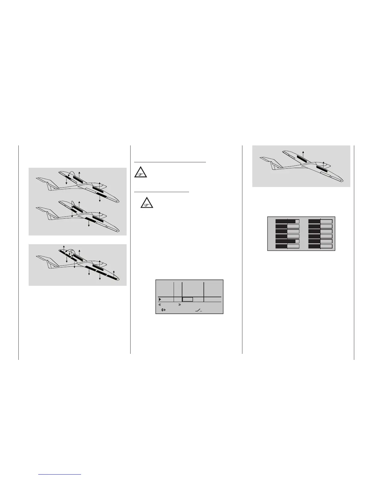
• “FLAP” and – if present – “FLAP2” column
As the model is braked on the landing approach,
both pairs of flaps can be set to deflect by different
amounts, e. g.:
AI
FL
FL2
FL2
FL
AI
AI
FL
FL2
FL2
FL
AI
• Combining AILE(2) and FLAP(2) for “Crow”
AI
FL
FL2
FL2
FL
AI
Though the airbrake mixers are set as described
above, there is a special flap constellation, called
“crow position” or “buttery”, that can also be set.
This airbrake setting causes both ailerons move
moderately upward while the aps move down-
ward as far as possible. Another mixer – see be-
low, under the section “Elevat. curve” – is then used
to trim the elevator such that the flight speed does
not change significantly in comparison to the nor-
mal flight position. Otherwise, there is a danger that
the model loses too much speed and then, after the
braking system is retracted (e. g. to extend a land-
ing approach that was too short, for example), pan-
cakes or even stalls.
A tip for “seeing” the effect of brakes:
Lift the aps and look over and under the
surface from the front. The larger the surface
projected by the lifted ap, the greater the
braking effect achieved.
Tips for activating airbrakes:
•
When, in addition to aileron and camber
ap servos, there is also a built-in servo
for actuating wing airbrakes, it can be
most simply connected to that receiver output – if
free – whose input has been selected for the brake
function, i. e. either on 1, 7, 8 or – if present – 9. If
this is not possible then, as an alternative, use a
free mixer to connect the selec ted brake control
channel with the airbrake servo.
• To activate two airbrake servos, the best ap-
proach is to leave one servo on output 1 and to
connect the second servo to a free output of your
choice – for example, output 9. You then also as-
sign this output to transmitter control 1 (as stand-
ard) on the »Control adjust« menu, page 112,
see gure.
In5
offset
0%
0%
0%
–––
0%
In6
In7
In8
–––
–––
–––
GL
GL
GL
GL
typ
normal
fr
fr
fr
SEL
Cn1
As you do, leave the settings for offset, travel, etc.
at their default values. Also leave the default “GL”
value in the column labelled “TYP” so that the se-
cond airbrake, like the rst, operates in the same
way across all ight phases.
AI
FL
FL
AI
Servo 1
Servo 9
You can assure yourself that this works as stated
by accessing the »Servo display« menu, accessi-
ble from almost any menu level with a brief simul-
taneous tap on the keys on the left four-way
button, see page 274:
1
3
5
7
+
0%
0%
9
11
0%
0%
2
4
6
8
+
0%
0%
0%
0%10
12
0%
0%
+100%
+100%
If this relatively simply variant should prove impos-
sible for whichever reasons, then the alternative is
a solution with two free mixers – and potentially in-
volving the »Mix-only channel« menu, see page
212, which is available as standard on the mc-
20 HoTT transmitter only. and potentially involv-
ing
The airbrake travels must then be ne-tuned on
the »Servo adjustment« menu, page 106.

 Loading...


