182
Program description - Wing mixers
D.red (Differential reduction)
Elevat curve
Brake settings
AILE
Crow
D.red
0%
0%
0%
0%
0%
0%
FLAP FLAP2
normal
Earlier, we discussed the problems with the butterfly
(crow) configuration. Namely: that with the use of ailer-
on differential, the aileron effect can be strongly (nega-
tively) affected by the aileron elevation. This is firstly
because further deflection of the one aileron upwards
is (almost) no longer possible and secondly because
the downward-deflected aileron – depending on the
elevation and degree of differential configured – is often
unable to achieve even its “normal” position.
To be able to restore the effect of the aileron
altered in this way as far as possible, you
should ensure that you make use of the auto-
mated “Differential reduction” feature. This feature
continuously reduces the degree of aileron differential
as the airbrake system is extended. The feature is
configurable and can even be set to suppress differen-
tial entirely.
A value of 0 % means that the “aileron differential” set
at the transmitter remains fully in force. An entry that
equals the % value set for aileron differential means the
differential is fully eliminated once the butterfly func-
tion is at maximum travel, i. e. with flaps fully extended.
Setting a reduction value greater than the aileron differ-
ential configured will eliminate the latter even before the
full travel of the airbrake stick.
Values can be set in the range 0 to 150 %.
A simultaneous tap on the or keys of the right
four-way button (CLEAR) will reset a changed value in
a given active (inverse video) field back to 0 %.
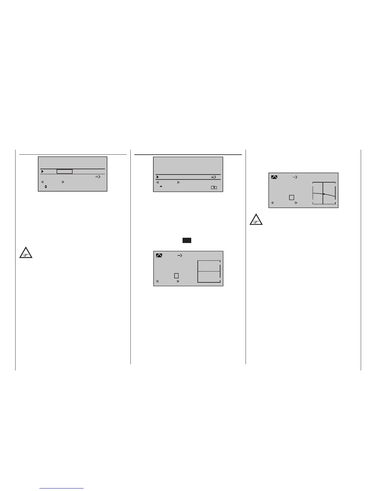
Elevat curve (Brake elevator)
Elevat curve
Brake settings
Crow
D.red
0%
0%
0%
0%
0%
0%
normal
If the airbrake control – to be set to 1, 7, 8 or – if pre-
sent – 9 on the “Brake Offset” line of the »Model type«
menu, page 100 – is used to extend the flaps as
described previously for the “Brake settings” menu, this
will often have a negative effect on the aircraft model’s
airspeed. This mixer can be used to compensate this
type of effect by applying a corrective value to the
elevator.
A brief tap on the centre SET key of the right four-way
button will switch to the display screen shown below:
Input
Output
Point
?
–100%
0%
0%
Brake
normal
Ele
Curve
off
normal
Setting notices for “Elevat curve”
The offset set in the »Model type« menu, page 100,
affects this mixer:
The vertical line on the display that indicates the posi-
tion of the airbrake control only moves from the edge
of the graph when the configured offset is exceeded.
In doing so, airbrake control travel is automatically
expanded back to 100 %, as described in the »Model
type« menu.
Accordingly, the mixer’s neutral point always lies on the
left edge, independently of the offset configured.
Now adjust the elevator curve in the direction of the
opposite end-point in accordance with requirements.
Note that this method for setting the 6-point curve
mixer follows the same principles that are applicable to
the curve mixers, already described on page 134 in
the context of the »Channel 1 curve« menu.
Input
Output
Point
1
–19%
–6%
–7%
Brake
normal
EL
Curve
on
The selected setting should certainly be tried
out in sufficient altitude and, if necessary,
readjusted. When doing this, be sure to pay
attention that the model does not slow down too much
while the brake system is extended! Otherwise, you run
the risk that, after the braking system is retracted, e. g.
to extend a landing approach that was too short, for
example, your model pancakes or even stalls.

 Loading...


