187
Program description - Helicopter mixer
Trim x-axis function
This function is activated by tapping the left () or
right () selection key of the right four-way button with
an active (i. e. inverse video) value field. You can then
use the selection keys on the right four-way button to
reposition the active point horizontally or vertically as
you wish. In the figure below, “Point 1” which was just
shifted to +25 % with the trim point function, will now
be shifted to the left:
?
0%
+57%
normal
Pitch
+25%
Trim X-axis
Input
Output
Point
Notes:
•
If the point is repositioned horizontally fur-
ther away from the current control position
than approx. ±25 %, a “?” sign will reap-
pear in the line Point. This question mark does not
refer to the repositioned point, however: instead, it
signies that a further point can be set at the cur-
rent control position.
• Please note that the percentage value on the
“Output” line always relates to the current stick po-
sition and not to the position of the point.
Smoothing the collective pitch curve
In the example below, sample reference points have
been set …
reference point 1 to +50 %,
reference point 2 to +75 % and
reference point 3 to -50 %
… as described in the last section:
+50%
–50%
–50%
3
Pitch
normal
Input
Output
Point
Curve
off
This “jagged” curve profile can be smoothed automati-
cally simply by pressing a button.
Starting from the situation shown in the previous illus-
tration, disable the Value field by pressing the central
ESC button of the left-hand four-way button, or the
SET button of the right-hand four-way button.
Now use the arrow buttons of the left or right-hand
four-way button to move the marker frame up to the
“Curve” line, and press the central SET button of the
right-hand four-way button once more to activate the
Value field of the “Curve” line:
+50%
–50%
–50%
3
Pitch
normal
Input
Output
Point
Curve off
Now use the arrow buttons of the right-hand four-way
button to set the Value field from “off” to “on”, and then
briefly press the central SET button of the right-hand
four-way button, or the central ESC button of the left-
hand four-way button, to conclude the procedure:
+50%
–50%
–50%
3
Pitch
normal
Input
Output
Point
Curve
on
Notes:
•
If the stick does not coincide with the ex-
act reference point, please note that the
percentage value on the “Output” line al-
ways relates to the current stick position.
• The gures on these pages show control curves
created only for the purpose of illustration. Please
note, therefore, that the curve characteristics dis-
played do not in any way represent real-life col-
lective pitch curves. A specic application exam-
ple can be found in the programming examples on
page 324.
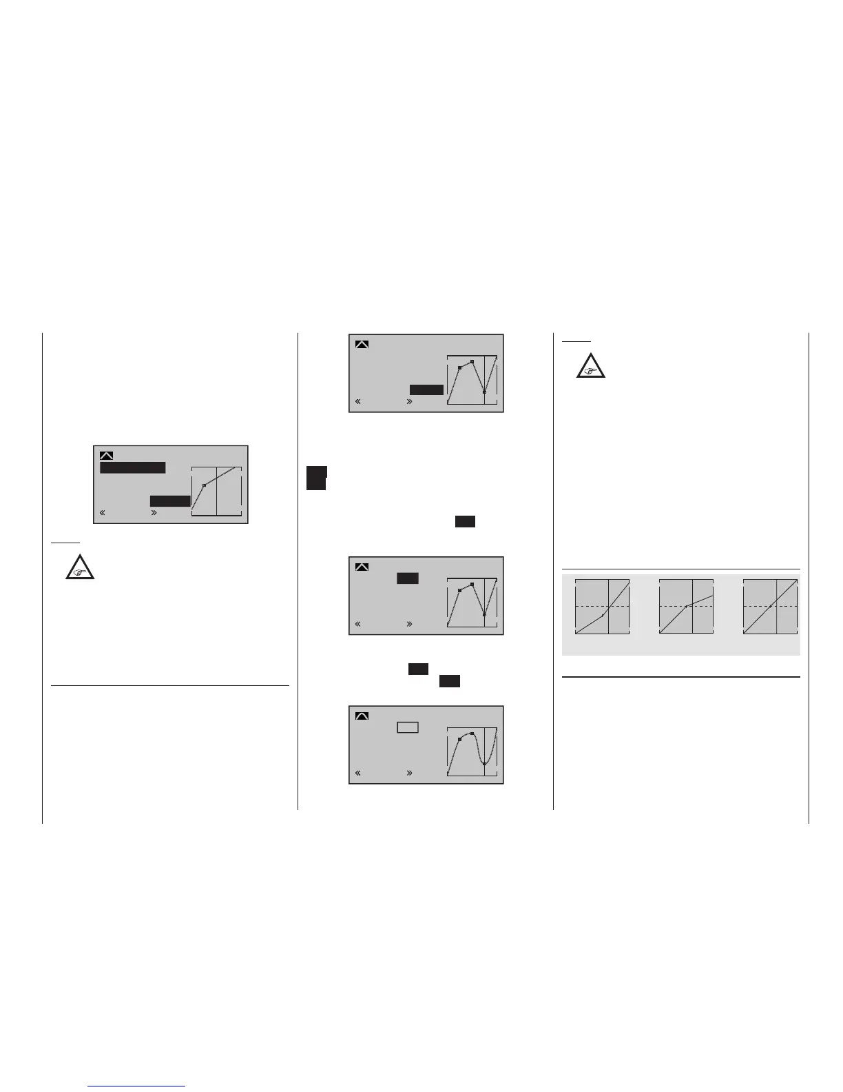
The following three graphs show typical 3-point pitch
curves for various flight phases, such as hovering,
aerobatics and 3D flight.
The vertical bar depicts the current stick position.
Please note that trim values greater than +100 % and
less than -100 % cannot be presented in the display.
Sample collective pitch curves for various ight phases:
+100% +100% +100%
-100%
-100%
-100%
Output
Output
Output
2 3 4 51
2 3 4 51
2 3 4 51
Control travel Control travel Control travel
Hover
Aerobatics 3D
Erasing reference points
To delete one of the reference points (1 to max. 4), use
the stick to move the vertical line into the vici nity of the
reference point in question. As soon as the reference
point number and its associated value is shown on the
“Point” line (see screen image above), following activa-
tion of the value field on the “Point” line now in inverse
video with a simultaneous tap on the or keys
of the right four-way button (CLEAR) it can be erased.

 Loading...


