188
Program description - Helicopter mixer
Complete the operation with a brief tap on the centre
key ESC of the left four-way button.
The “L” and “H” points, on the other hand, CANNOT
be deleted.
C1 Throttle (Throttle curve)
+50%
+50%
+50%
C1
Thro
normal
?
Input
Output
Point
Curve
off
Unlike the »Channel 1 curve« menu, this display is
only associated with the control curve of the throttle
servo, whereas the the “Channel 1 curve” affects all
servos controlled by the throttle/pitch stick.
Note that the output signal of the “Chan-
nel 1 curve” menu thus functions as an
input signal for the throttle curve pro-
grammed here: In the graph, the vertical line is
synchronized with the throttle/collective pitch
stick and therefore follows the current Channel 1
curve characteristic.
The throttle curve can also be defined (separately
per flight phase) by up to 6 points, termed “reference
points”, placed at any point along the stick travel.
The reference points are defined, adjusted and erased
in the usual way, as explained in the previous section
on the collective pitch curve. Start by defining the throt-
tle curve with three points, namely the points “L” and
“H” at the extremes, plus the Point “1” still to be set in
the control centre in order to match the motor power
curve to the collective pitch curve.
Helicopter with carburettor or electric drive sys-
tem with speed CONTROLLER
This setting relates only to the control curve of the
throttle servo or the speed controller.
Setting the throttle curve to suit a helicopter equipped
with a speed governor is discussed in the following
section.
As with the configuration of the collective pitch curve
(see previous page), the throttle curve can also be
defined by up to 6 points.
• In each case, set the control curve so that when the
throttle/collective pitch stick is in its end position,
the carburettor is fully open or the controller of an
electrically-powered helicopter is set to maximum
(except for auto-rotation flight, see page 198).
• For the hover point, which is normally at the control
centre, the carburettor setting or power control for
the speed controller must be matched to the collec-
tive pitch curve so that the correct system rotational
speed is obtained.
• At the minimum position of the throttle/collective
pitch stick, the throttle curve must first be config-
ured so that a glow motor runs at a speed consid-
erably higher than idle speed and the clutch is firmly
engaged.
Starting and stopping of the mo-
tor – whether combustion or electric drive –
should always take place within the given
ight phase as a consequence of the throttle
limiter and the “Cut Off trim” option of the digital
trim (see below).
This makes it unnecessary to program the two flight
phases that may be familiar to you from using other
remote control systems – namely “with idle-up” and
“without idle-up”, and with the associated “waste” of a
flight phase for this purpose – since the program of the
transmitters
mc-16 HoTT and mc-20 HoTT of-
fers a much more flexible approach to fine-tuning and
optimizing increases to system rotational speed below
the hover point than the “idle-up” approach.
Ensure that the throttle limiter is closed before starting
a motor with carburettor, i. e. so that the carburettor
can be adjusted within the idle range only with trim.
Ensure that you follow the safety instructions on page
197 at all times. If the throttle is set too high when
switching on the transmitter, you will receive audible
and visible warnings!
STARLET
#02
2:22h
Stp
Flug
K78
0:00
0:00
5.5V
3.9V
99%
«normal »
M
Throttle
too
high !
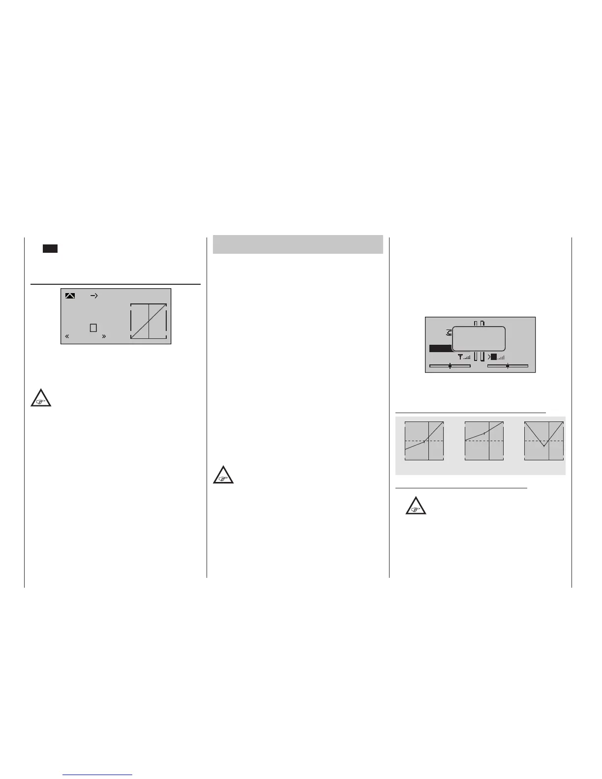
The following three graphs show (typical) 3-point throt-
tle curves for various flight phases, such as hovering
aerobatics and 3D flight.
Sample throttle curves for various ight phases:
+100% +100% +100%
-100%
-100%
-100%
Output
Output
Output
2 3 4 51
2 3 4 51
2 3 4 51
Control travel Control travel Control travel
Hover
Aerobatics 3D
Notes on using the “throttle limit” function:
•
The throttle limit function should be used
in any case (»Control adjust« menu,
page 122). At the rear limit of the default
transmitter control, the right-side throttle limit pro-
portional rotary slider, the throttle servo is com-
pletely decoupled from the throttle curve, the mo-
tor is at idle and will respond only to C1 trim. This
option permits the motor to be started in any ight
phase and to shut the motor off with the “Cut Off
trim” option of the digital trim. See below and/or

 Loading...


