189
Program description - Helicopter mixer
page 62.
Once the motor has started, push the throttle lim-
iter
slowly in the direction of the opposite end-
point to put actuation of the throttle servo fully un-
der the control of the throttle/collective pitch stick
once again. In order to prevent the throttle ser-
vo from being restricted by the throttle limiter in
the full throttle direction, set control travel on the
plus-side of the column labelled “travel” to +125 %
in the “Lim.” line of the »Control adjust« menu.
Leave the default value of “GL” in the “Type” col-
umn alone, however, to congure this setting glob-
ally for all ight phases.
For a more nely-tuned control travel curve for the
throttle limit control, you can also use the “Expo
throttle limiter”, page 104. This gives you the op-
tion of dening the idle setting at the throttle lim-
it control’s centre position, as readily determined
both visually and audibly.
Set the throttle limiter to its centre position and ad-
just the “EXPO thro lim.” value as far as is needed
until the motor is idling smoothly with the throttle
limit control set at its centre point. In this position,
the motor will then start without any problems.
To switch off, turn or push the throttle limit con-
trol – that is, without C1 cutoff trim – to its rearmost
end-point. As you do, ensure that the affected ser-
vo cannot hit an end-stop mechanically.
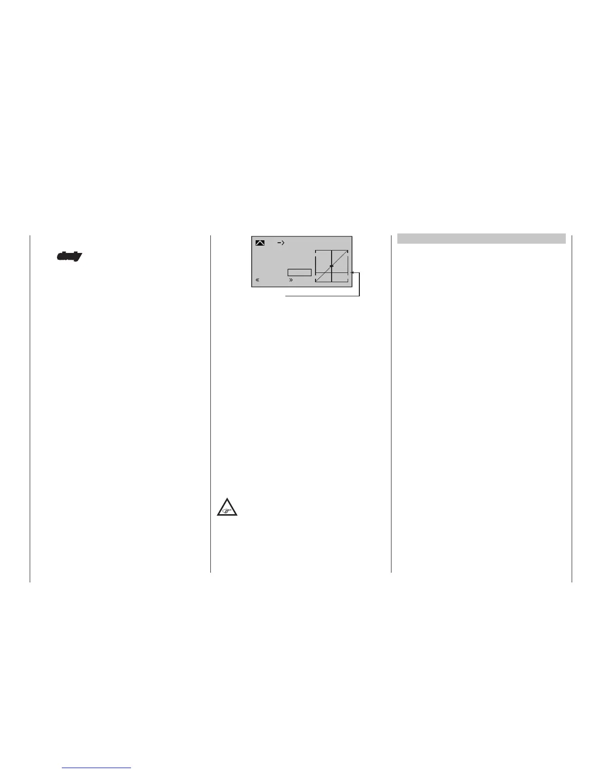
The throttle restriction set by the throttle limiter is
made visible as a horizontal bar in the diagram:
2
+50%
+50%
+50%
normal
Throttle limiter position
Input
Output
Point
C1 Thro
Curve
off
The output signal for the throttle servo can nev-
er be higher than that set by the horizontal bar. In
this example, about a maximum of +25 %.
• Since electric drive systems have no need for an
idle setting, the basic conguration of settings for
an electrically-powered helicopter merely involves
making sure that the control range of the throt-
tle limiter is both higher and lower than the adjust-
ment range of the speed controller (usually -100 %
to +100 %) by a safe margin. If necessary, there-
fore, adjust the “travel” setting of the throttle limiter
as appropriate on the “Lim.” line of the »Control
adjust« menu. Leave the default value of “GL” in
the “Type” column alone, however, to congure
this setting globally for all ight phases.
Fine-tuning of the throttle curve itself, however,
must take place in ight – as with a glow-powered
helicopter.
• If you wish to record the ight time of a (glow-pow-
ered) helicopter, you can assign a control switch
to the throttle limit slider, and then use this to
switch a timer on and off; see page 141.
For auto-rotation ight, an automatic
switch-over is made from this mixer to a
congurable default value; see page 198.
Helicopter with speed REGULATOR
Unlike speed controllers, which merely adjust output
level in a manner similar to a carburettor, a speed regu-
lator keeps speed in the system it monitors constant
by regulating its output autonomously. In the case of
combustion motor powered helicopters, the regulator
therefore controls the throttle servo itself as appropriate
or, for an electric helicopter, the motor’s speed control-
ler. Therefore, speed regulators do not need a tradi-
tional throttle curve but rather only a speed setting. A
deviation from the preset speed will therefore only take
place if the level of output required exceeds the maxi-
mum level available.
Usually, receiver output 8 is reserved for connecting a
speed regulator; refer to the receiver layout on page
67. However, if this connection is used there will
be no throttle limit function because the throttle limit
function can only be implemented via the “C1 Thro”
mixer which is on the – then unused – output 6.
To make the comfort and safety features of a throttle
limiter available, a speed regulator should be connect-
ed to receiver output 6 (contrary to the general connec-
tion notices) and only requires appropriate adaptation
to the throttle curve so it can take over the task of the
“conventional” transmitter control.
Since in this case the “throttle curve” only regulates
the target speed of the motor controller and this target
motor speed should typically remain constant over the
entire collective pitch adjustment range, the “C1
Thro” mixer must be used to set a horizontal line – i. e.
every (pitch) input value will result in the same (“throt-
tle”) output value – whose “height” is defined by the
target motor speed.
First, therefore, the reference points “1” to “4” – if pre-
sent and set – are erased.

 Loading...


