190
Program description - Helicopter mixer
Following this, the reference points “L” (input = 0 %)
and “H” (input = +100 %) are then each set to the same
value, for example:
0%
+65%
+65%
C1 Thro
normal
L
Input
Output
Point
Curve
off
The value to be set depends both on the speed con-
troller used and on the target motor speed that is
desired, and can, of course, be varied according to the
flight phase.
For auto-rotation ight, an automatic
switch-over is made from this mixer to a
congurable default value; see page 198.
C1 Tail (Static torque compensation)
0%
0%
0%
Tail
C1
normal
?
Input
Output
Point
Curve
off
The default approach here is to preset a torque com-
pensation curve with a linear mixer ratio of a uniform
0 %, as is required for a gyro sensor working in “head-
ing lock mode” – see the screen image above.
ATTENTION:
In this context, ensure that you comply
with the instructions on adjusting your
gyro: if not, you risk making adjustments
that render your helicopter impossible to y.
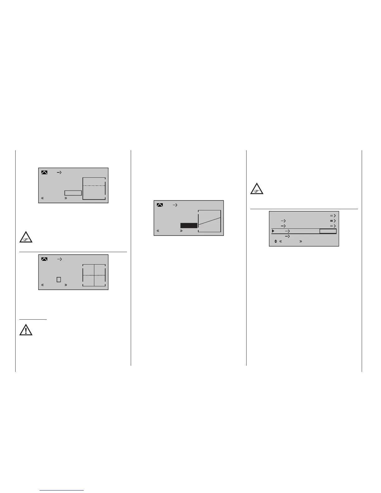
If, on the other hand, you use your gyro sensor in
the “normal” operating mode, or if it only has what is
termed “normal mode”, then configure the mixer as
follows:
Note that the output signal of the “Channel 1 curve”
option also functions as an input signal for the tail rotor
curve programmed here: In the graph, the vertical line
is synchronized with the throttle/collective pitch stick
and follows the current Channel 1 curve characteristic
from the »Channel 1 curve« menu.
In the auto-rotation ight phase this mixer
is automatically switched off, see page
198.
Tail Throttle
Pitch
0%
0%
SEL
normal
C1
C1
Throttle
Tail
Tail
Roll
Throttle
Throttle
While the tail rotor normally compensates for the effect
of main rotor torque on the fuselage, it is also used to
control the helicopter around the vertical axis. Increas-
ing tail rotor thrust requires a corresponding adjustment
to motor power, however, to avoid a fall-off in system
rotational speed.
This mixer sets the extent to which the throttle follows
the tail rotor. The throttle will follow on one side only, to
the side on which the tail rotor thrust is increased. The
setting range is therefore 0 to +100 %. The direction
depends on the main rotor’s direction of rotation (left or
right), and this must first be set correctly on the »Heli-
copter type« menu. For left-hand rotation systems, the
throttle follows the tail rotor when the tail rotor stick is
moved to the left, and vice versa for right-hand rotation
systems.
A simultaneous tap on the or keys of the right
four-way button (CLEAR) will reset a changed value in
an active (inverse video) field back to 0 %.
As with the configuration of the collective pitch curve
(see page 185), the control curve of the tail rotor can
also be defined by up to 6 points. If required, therefore,
you can modify the mixer at any time and preset both
symmetrical and asymmetric mixer ratios both above
and below the hover point. Before you do, however,
ensure you have entered the correct direction of ro-
tation for the main rotor on the »Helicopter type«
menu(see page 103).
+100%
+30%
Tail
C1
normal
H
+30%
Input
Output
Point
Curve
off
Starting with values of -30 % for point “L” and +30 %
for point “H”, the mixer is to be configured in such a
way that the helicopter, even during prolonged verti-
cally ascending or descending flights, does not deviate
from the yaw axis as a result of the main rotor’s altered
torque while hovering. For hovered flight, trim should
only be affected by way of the (digital) tail rotor trim
lever.
For a reliable torque compensation setting, it is es-
sential that the collective pitch and throttle curves have
been set up correctly, i. e. that the rotor speed remains
constant over the collective pitch’s full adjustment
range.
This third curve mixer applies only to the control curve
of the tail rotor servo when the throttle/collective pitch
stick is moved, whereas the “Channel 1 curve”, see
page 137, acts on all servos that are affected by the
throttle/collective pitch stick.

 Loading...


