193
Program description - Helicopter mixer
• Use a strong and comparably fast servo.
When the gyro sensor detects a model rotation, the
faster its response – a corresponding corrective change
to tail rotor thrust – takes effect, the further the gyro
gain adjuster can be moved without causing the tail
of the model to start oscillating, and the better the
model’s stability about its vertical axis. If the response
is slower, there is a risk that the model’s tail will start to
oscillate even at low gyro gain settings. Here, further
reductions to gyro gain will need to be made to elimi-
nate the oscillation.
If the model is flying forward at high speed or hovering
in a powerful headwind, the net result of the stabilizing
effect of the vertical fin combined with the gyro may
also lead to an overreaction that once again manifests
itself through tail oscillation. To achieve optimum gyro
stabilization under all conditions, you can make use of
the option to adjust gyro gain from the transmitter us-
ing a transmitter control assigned to input “7”, in con-
nection with gyro suppression and/or the two settings
on the Gyro NEJ-120 BB.
Further notes on gyros with congurable multilevel
gyro gain (e. g. NEJ-120 BB)
Since you cannot specify the gyro gain from the
transmitter proportionally via the transmitter control,
the gyro’s own control 1 must be used to set the
(weaker) gyro gain (e. g. for aerobatics) and control 2
the stronger gyro gain (e. g. for hovered ight). Even
though a proportional control is used for control func-
tion 7, only a switch-over between these two values
takes place and the setting is therefore not propor-
tional.
0%
0%
SEL
0%
0°
normal
0%
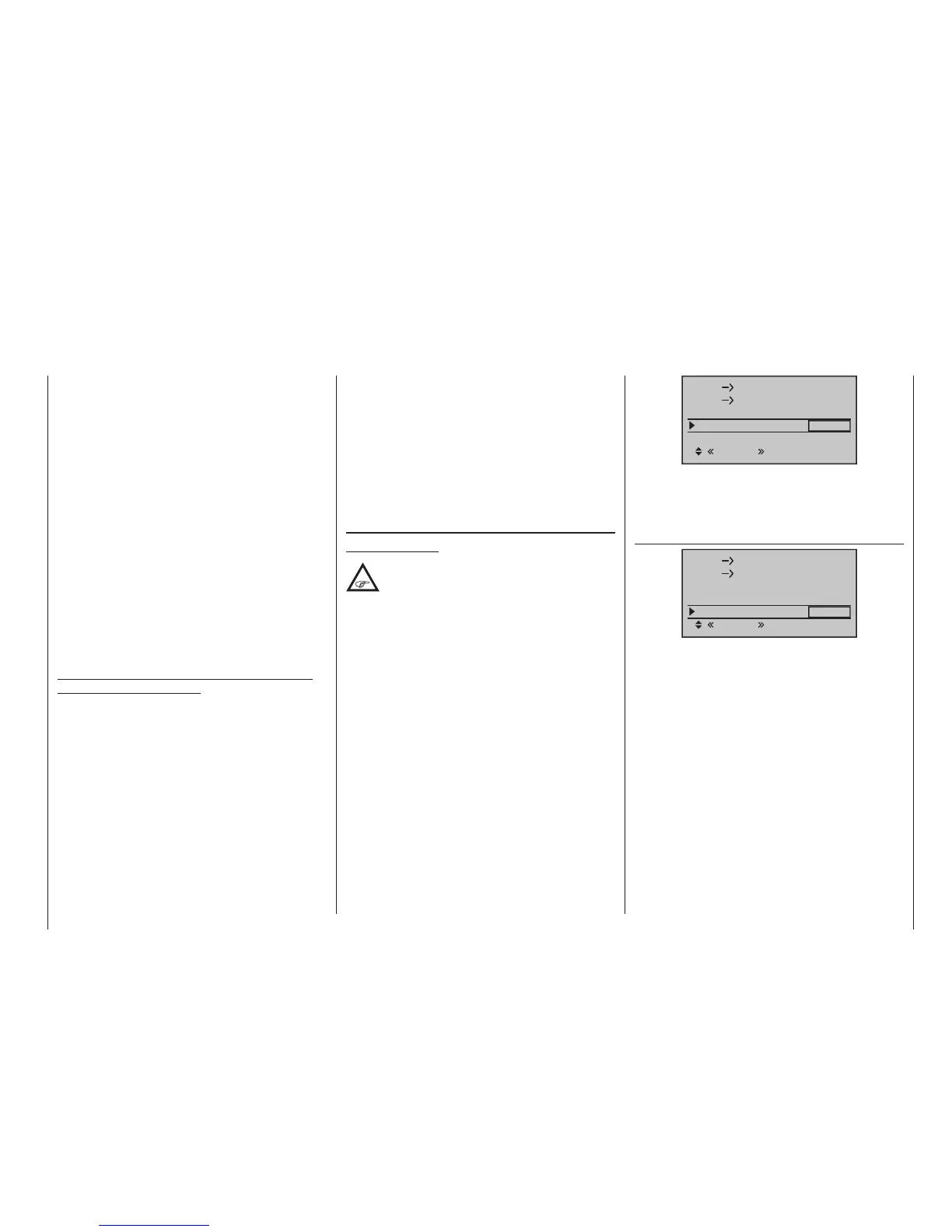
Nick
Nick
Throttle
Tail
Swash rotation
Gyro suppress
Gyro gain
Based on these flight-phase specific (offset) settings,
gyro gain can also be infinitely varied by a transmit-
ter control assigned in the “Gyro” line of the »Control
adjust« menu, page 120.
Swash rotation
0%
0%
SEL
0%
0°
normal
0%
Nick
Nick
Throttle
Tail
Swash rotation
Gyro suppress
Gyro gain
Some rotor head control systems make it necessary
to incline the swashplate in a different direction from
the intended inclination of the rotor plane when a cyclic
control command is given. If your model features a
four-bladed main rotor, for example, you may need to
use this menu to set up a software-driven 45 ° rotation
of the control linkage to the right, so that the push-
rods from the swashplate to the rotor head can be set
exactly vertical, ensuring that the blade control system
works correctly, without unwanted differential effects.
This eliminates the need to make mechanical changes
to the control linkages. Negative angles equate to a vir-
tual rotation of the rotor head to the left; positive angles
a virtual rotation to the right.
You should therefore advance control 2 to the point
where the model is on the brink of oscillating when
hovering in calm conditions, and advance control 1 to
the point where the model does not oscillate with its
tail even when ying at maximum speed into a strong
headwind. Depending on the state of the weather
and the ight program planned, you can also switch
over the gyro gain from the transmitter – also with
gyro suppression dependent on tail rotor deection if
required.
Gyro gain (Gyro Offset)
Important notice:
The value of this option is identical to the
offset value set in the “Gyro” line of the
»Control adjust« menu, page 120. For
this reason, any changes made always affect the
other menu directly – and vice versa.
Most of the latest gyro systems not only feature infi-
nitely variable proportional gyro gain setting, but also
offer a choice of two separate types of gain mode on
the transmitter.
If the gyro in use has at least one of these features then
this alternative offset setting provides an opportunity to
preset both “normal” gyro gain as well as, as appropri-
ate, to specify a “heading-lock mode” whereby, even
within this pre-selection, gyro gain can be reduced by
a particular gain type for normal, slow flight with maxi-
mum flight stabilization, fast circuit flights and aerobat-
ics.
To proceed as described above, use flight phase
switching to enter different settings on the “Gyro
offset” line. Values between -125 % and +125 % are
possible:

 Loading...


