192
Program description - Helicopter mixer
The gyro suppression function reduces gyro gain in a
linear progression as the pilot increases the tail rotor
deflection. Without gyro suppression – i. e. when set to
0 % – the gyro effect is constant, regardless of the stick
position.
With a transmitter control assigned on the “Gyro” line
on the »Control adjust« menu, page 120, e. g. one
of the proportional sliders mounted in the middle con-
sole; as applicable, also made flight-phase depend-
ent and/or with infinitely variable gyro effect between
minimum and maximum. In this case, gyro gain is
maximum at full deflection of the slider, and zero at the
opposite end-point.
Of course, the software lets you limit the gyro gain
range on both sides by altering the transmitter con-
troltravel.
Depending on the transmitter control’s position, the
gyro gain at full travel on the tail rotor stick is:
“current control position
minus
gyro suppression value”.
Accordingly, if the transmitter control is at the neutral
point, and gyro suppression is set to 100 %, the gyro
gain is reduced to zero as the tail rotor deflection in-
creases. For values between 100 % and the maximum
value of 199 %, the gyro can be fully suppressed – de-
pending on the transmitter control position – well before
full deflection of the tail rotor; see the diagram on the
next page.
For the Graupner gyro NEJ-120 BB, No. 3277, both
the upper and the lower values are set via rotary con-
trols: control 1 sets the minimum gyro gain at the bot-
tom position of the slider; control 2 sets the maximum
gain at the top end-point of the slider; the transition
between these two values occurs roughly in the middle
of the slider travel.
Exemple:
+50 %
Gyro gain
left
Stick deflection tail rotor
centre right
Range of
transmitter
control 7
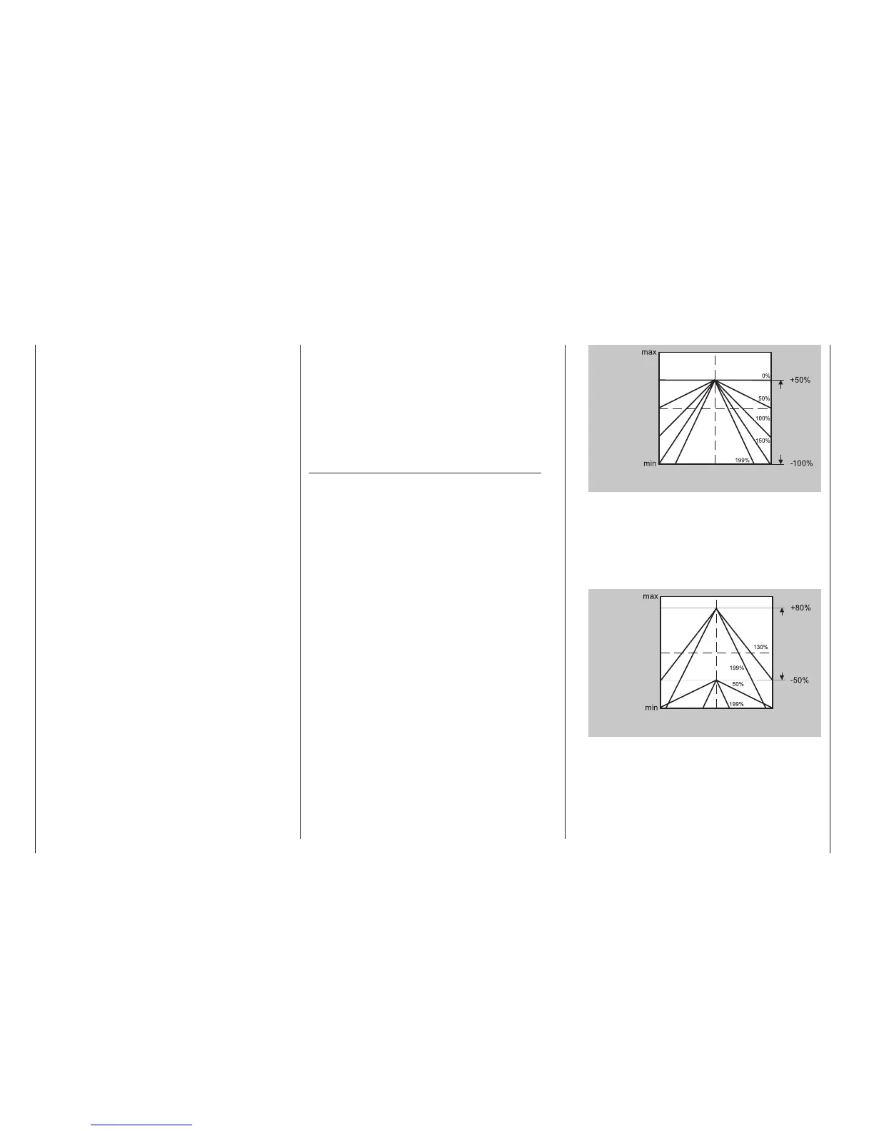
• Linear gyro suppression with reduced control trav-
el, e. g. -50 % to +80 % of full travel.
Gyro gain is innitely variable within these trans-
mitter control limits. Here too, for purposes of il-
lustration, we plot gyro gain values in relation to
tail rotor deection for various parameter values of
gyro suppression.
Exemple:
+80 %
Gyro gain
left
Stick deflection tail rotor
centre right
Range of
transmitter
control 7
Adjusting the gyro sensor
To achieve the maximum possible level of stabilization
for the helicopter with the gyro along the vertical axis,
observe the following:
• The controls should have as little friction and “play”
as possible.
• There should be no “spring” in the control linkage.
In contrast, the PIEZO 900, PIEZO 2000 and PI-
EZO3000 gyro systems feature proportional, infinitely
variable adjustment of gyro gain; see below for typical
diagrams.
As an example, the option to configure flight phase-
specific – and static – gyro gain gives you the opportu-
nity to exploit maximum stabilization for normal, slow
flying, but to reduce gyro gain for fast circuits and
aerobatics.
Samples of various gyro settings and conguration
• Linear gyro suppression: 0 % to 199 %.
With the tail rotor stick in the centre position,
the resulting gyro effect is set using the select-
ed transmitter control. Using a proportional rotary
control or slider, the effect is innitely variable be-
tween zero (“min”) and maximum (“max”), provid-
ed transmitter control travel is not restricted. With
full tail rotor deection, the effective gyro gain is
as follows:
“current control position
minus
gyro suppression value”.
This means that at 0 % gyro suppression, gyro
gain is constant for tail rotor stick movement; at
50 % suppression, gyro gain is reduced to half
if the assigned transmitter control is moved to
the +50 % position (as shown here); and only at
>150 % suppression is gain reduced to zero with
the slider at this position, well before full tail rotor
deection.

 Loading...


