242
Program description - Telemetry
Factory setting: 0.75 s.
FAIL SAFE ALL (global fail-safe setting)
This sub-menu allows servo fail-safe positions to be
established at the “push of a button” in a similar man-
ner to that described on page 216 for the »Fail Safe«
menu.
Switch to the “FAIL SAFE ALL” line and activate the
value field by touching the centre SET key of the right
four-way button. “NO” will be displayed in inverse
video. Then adjust the parameter to “SAVE” with one
of the selection keys of the right four-way button. Now,
using the operating elements of the transmitter, move
all servos to the desired fail-safe position you assigned
or want to assign in the line “MODE” “FAI(L) SAFE”. The
current position of the control for the channel which
was just set is shown in the bottom “Position” line:
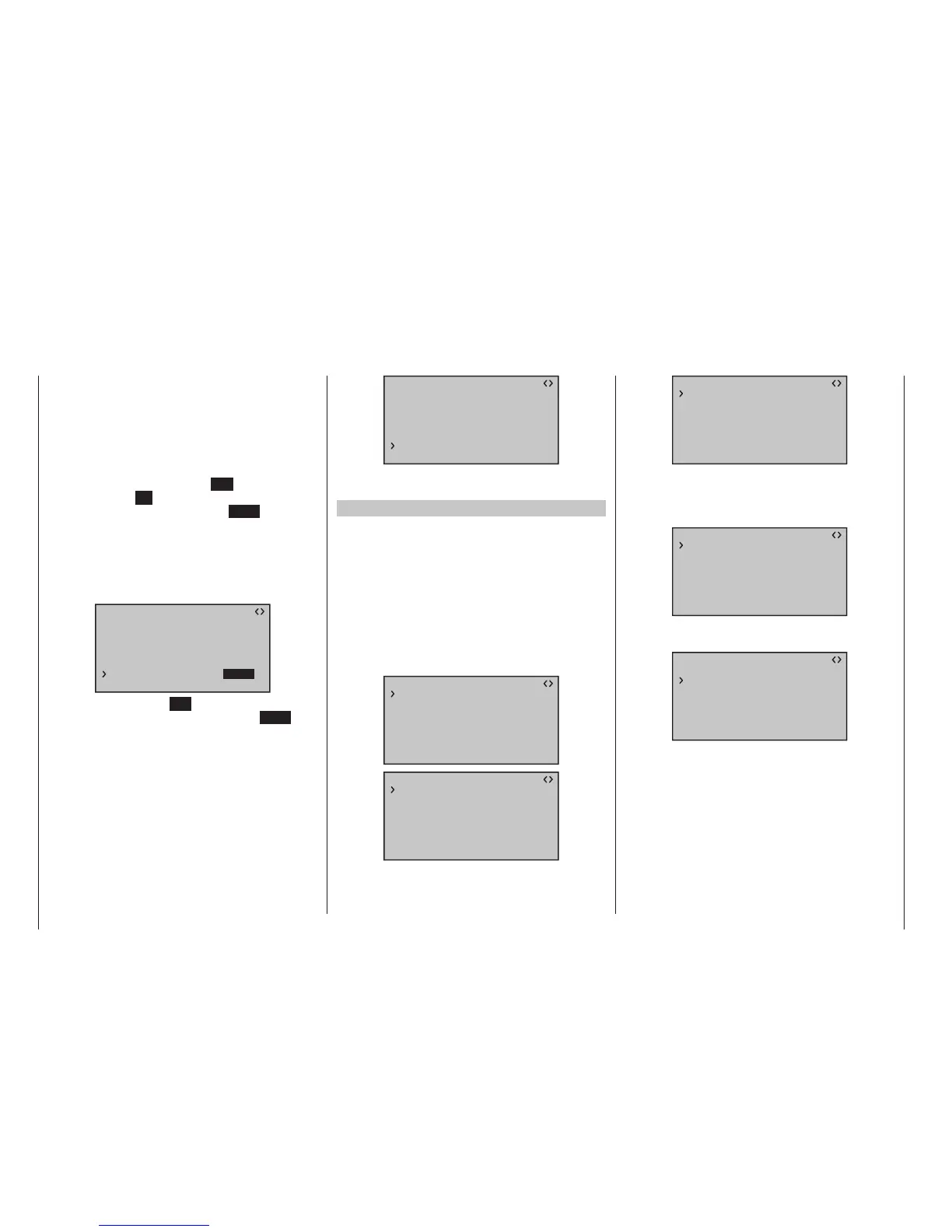
RX FAIL SAFE V3.78
INPUT CH: 01
MODE : FAI-SAFE
F.S.POS. : 1500µsec
DELAY : 0.75sec
OUTPUT CH: 01
POSITION : 1670µsec
FAIL SAFE ALL: SAVE
After a tap on the centre SET key of the right four-way
button, the display will change again, from “SAVE” to
“NO”. The saved the positions of all servos affected by
this measure and adopted them in parallel to the line
“F.S.Pos.” and the display then immediately shows the
following for the current OUTPUT CH (servo connec-
tion):
RX FAIL SAFE V3.78
INPUT CH: 01
MODE : FAI-SAFE
F.S.POS. : 1500µsec
DELAY : 0.75sec
OUTPUT CH: 01
POSITION : 1670µsec
FAIL SAFE ALL: NO
Switch off the transmitter and check the fail-safe posi-
tions based on the servo throws.
“Fail Safe” in combination with “Channel Mapping”
In order to ensure that the mapped servos – that is to
say servos which are controlled from a common con-
trol channel (INPUT CH) – react the same way even in
the event of a failure, the corresponding settings of
the INPUT CH determine the behavior of the mapped
servos!!!
Therefore, the servo connections 6, 7 and 8 of a receiv-
er are mapped, for example, with one another, whereby
the OUTPUT CH (servo connections) 06, 07 and 08 are
assigned as INPUT CH of the same respective control
channel “04” …
RX FAIL SAFE V3.78
INPUT CH: 04
MODE : OFF
F.S.POS. : 1670µsec
DELAY : 0.75sec
OUTPUT CH: 06
POSITION : 1670µsec
FAIL SAFE ALL: NO
RX FAIL SAFE V3.78
INPUT CH: 04
MODE : OFF
F.S.POS. : 1230µsec
DELAY : 0.75sec
OUTPUT CH: 07
POSITION : 1670µsec
FAIL SAFE ALL: NO
RX FAIL SAFE V3.78
INPUT CH: 04
MODE : HOLD
F.S.POS. : 1770µsec
DELAY : 0.75sec
OUTPUT CH: 08
POSITION : 1670µsec
FAIL SAFE ALL: NO
… the INPUT CH 04 determines the fail-safe behavior
of these three servos connected to the control channel
4 completely independently of the individual settings of
the respective OUTPUT CH:
RX FAIL SAFE V3.78
INPUT CH: 04
MODE : FAI-SAFE
F.S.POS. : 1500µsec
DELAY : 0.75sec
OUTPUT CH: 04
POSITION : 1500µsec
FAIL SAFE ALL: NO
This is also the case, for example, if this is mapped
with INPUT CH 01:
RX FAIL SAFE V3.78
INPUT CH: 01
MODE : FAI-SAFE
F.S.POS. : 1500µsec
DELAY : 0.75sec
OUTPUT CH: 04
POSITION : 1500µsec
FAIL SAFE ALL: NO
In this case, the servo connection 04 would, in turn,
react according to the fail-safe settings of CH 01.
The reaction or delay time set in the “DELAY” line, on
the other hand, always applies uniformly for all chan-
nels set to “FAI(L) SAFE”.
 Loading...


