246
Program description - Telemetry
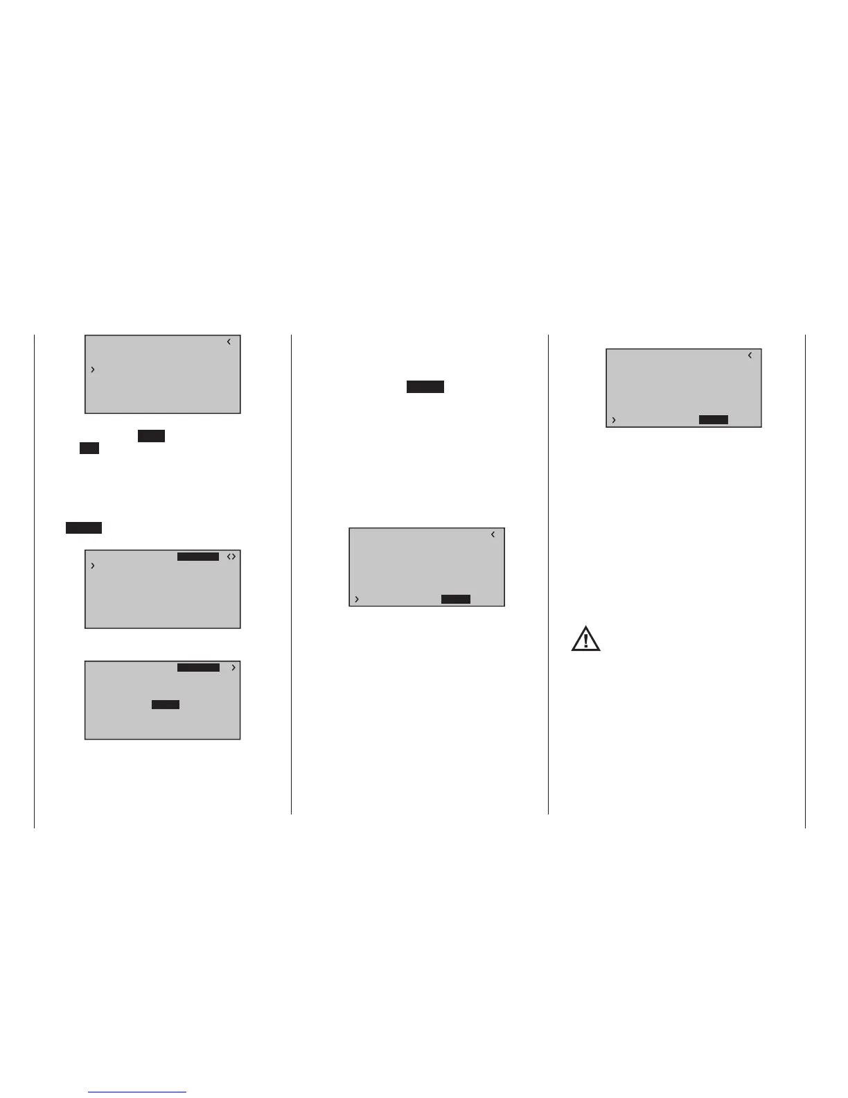
RX SERVO TESTV3.78
ALL–MIN : 1000µsec
ALL–MAX : 2000µsec
ALARM VOLT : 3.8V
ALARM TEMP–:–10°C
ALARM TEMP+: 55°C
CH OUT TYPE:ONCE
TEST : START
To stop the servo test, reactivate the entry field as de-
scribed above, select STOP and confirm this selection
with the SET key of the right four-way button.
ALARM VOLT (receiver undervoltage warning)
The receiver voltage is monitored through ALARM
VOLT. The interval can be adjusted between 3.0 and
7.5 Volt. If the set alarm threshold is undercut, an
acoustic signal is issued (interval peep tone long/short)
and “VOLT.E” blinks in the top right of all »RX …«
displays:
RX SERVO
REVERSE : OFF
CENTER : 1500µsec
TRIM : –000µsec
TRAVEL– : 150%
OUTPUT CH: 01
TRAVEL+ : 150%
PERIOD : 20msec
VOLT.E
The parameter “R-VOLT” is also represented inversely
in the »RX DATAVIEW« display:
S–STR100% R–TEM.+28°C
L PACK TIME 00010msec
L.R-VOLT:03.5V
S–QUA100%S–dBM–030dBM
SENSOR1 :00.0V 00°C
SENSOR2 :00.0V 00°C
R-VOLT :03.7V
RX DATAVIEW VOLT.E
ALARM TEMP +/-
(recommended temperature monitoring)
These two options monitor the receiver temperature.
Alower threshold “ALARM TEMP-” (-20 … +10 °C)
and an upper threshold “ALARM TEMP+” (50 … 80 °C)
can be programmed. When these specifications are
exceeded or undercut, an acoustic signal (continuous
peep tone) sounds and “TEMP.E” appears in the top
right of all receiver displays. In addition, the parameter
“R-TEM” is shown inversely on the “»RX DATAVIEW«“
display page.
Make sure that your receiver remains within the per-
missible temperature range during all flight conditions
(ideally between -10 and 55 °C).
CH OUTPUT TYPE (connection type)
Here you select how the receiver outputs are con-
trolled.
• ONCE
RX SERVO TEST V3.78
ALL–MIN : 1000µsec
ALL–MAX : 2000µsec
ALARM VOLT : 3.8V
ALARM TEMP–:–10°C
ALARM TEMP+: 55°C
TEST : START
CH OUT TYPE:ONCE
The servo connections of the receiver are controlled
successively. This is recommended for analog ser-
vos.
This setting automatically operates servos in a
20 ms cycle – or in a 30 ms cycle for a 12 channel
GR-24 receiver (No. 33512) – , regardless of what
is set or displayed in the “PERIOD” line of the »RX
SERVO« screen!
• SAME
RX SERVO TEST V3.78
ALL–MIN : 1000µsec
ALL–MAX : 2000µsec
ALARM VOLT : 3.8V
ALARM TEMP–:–10°C
ALARM TEMP+: 55°C
TEST : START
CH OUT TYPE:SAME
The signals are passed to the receiver servo sock-
ets in parallel blocks. For example, the control sig-
nals are sent simultaneously to the servos con-
nected to sockets 1 to 4 and 5 to 8 of the GR-16
receiver (No. 33508), and the servos connected to
sockets 1 to 4, 5 to 8 and 9 to 12 of the GR-24 re-
ceiver (No. 33512).
This is recommended for digital servos when mul-
tiple servos are used for one function (e. g. aileron),
so that the servos can run absolutely synchronized.
When only using digital servos, we recommend
setting the “PERIOD” line of the »RX SERVO« to
10 ms in order to be able to utilize the fast reaction
of digital servos. With the use of analog servos or in
mixer mode, 20 ms must be selected!
With this setting, pay particular atten-
tion to the sufcient dimensioning of
the receiver current supply. Since up to
four servos can always operate simultaneously, the
requirement is higher.
• SUMO (sum signal OUT)
A HoTT receiver configured as SUMO permanent-
ly generates a so-called sum signal from the con-
trol signals of all of its control channels and provides
this by default in the case of the receivers supplied
as standard in the sets GR-16 (No. 33508) at servo
socket 6 and GR-24 (No. 33512) at servo socket 8.

 Loading...


