314
Programming examples - Delta and ying wing
»Wing mixers« (beginning on page 166)
… menu, and enter the values for the ailerons to be
raised and the “flaps” to be lowered in the “Crow” line
so that the occurring moments compensate one an-
other and the altitude of the model remains stable. In
the process, however, you should leave the flaps with
enough “play” for the elevator function!!! Therefore, do
not utilize the entire servo travel for the crow alone; for
example:
Elevat curve
Brake settings
AILE
Crow
D.red
+55%
0%
0%
–44%
0%
0%
FLAP FLAP2
Normal
You can ignore all other settings in this menu.
Note:
The “Brake settings” menu is switched “off” if:
“Motor on C1 forward / back” in the »Model
type« menu, page 98, AND the “Motor”
column of the »Phase settings« menu, page 148,
are set to “yes” for the currently active ight phase.
Change the ight phase, if applicable.
Similarly, a modern, tapered flying wing air craft can
also be operated. With some of these models there are
also interior and exterior rudders: The prior is in front of
the centre of gravity and the latter is behind. A down-
ward throw of the central rudder(s) increases the as-
cending forces and has an elevator effect. An upward
throw has the opposite effect. On the exterior ailerons,
on the other hand, the effect is just the opposite: A
downward throw shows an elevator effect and vice
versa. With appropriate adjustment of the “leading”
mixer to the setting of curve mixers in order to achieve
a supporting effect from the external rudder pair with
only extreme stick deflection in the height/depth direc-
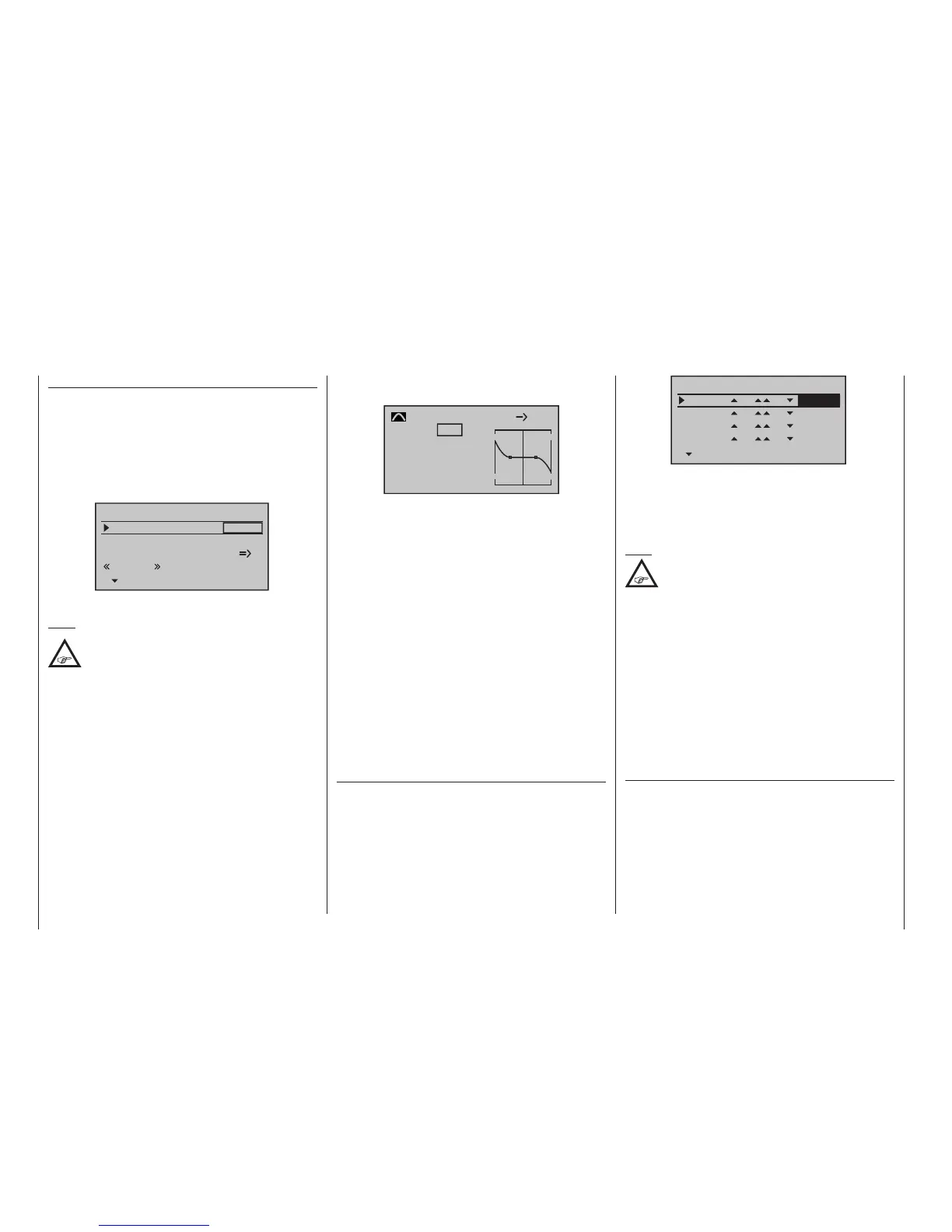
tion, “everything” is possible here. The author of this
manual uses a curve mixer for his model, which is
defined by a total of four points:
0%
0%
Input
Output
Point
C.Mix 9
normal
Curve
EL 5
0%
on
?
In this example the two interpolation points 1 and 2 are
each at 0 % as well as the left edge point at +60 % and
the right edge point at -65 %. In conclusion, the curve
was rounded.
In this case: Regardless of which type of servo ar-
rangement was selected, any type of differentiation
should be set with caution! On a tail-less model, dif-
ferentiations show a single-sided height/depth elevator
effect, so we urgently recommend beginning at least
the initial flights with a setting of 0 %! Over the course
of the further flight testing, under certain circumstances
it may be advantageous to experiment with differentia-
tions deviating from zero.
With larger models, rudders in the winglets – the “ears”
mounted on the wing ends – can be beneficial. If these
are controlled with two separate servos, one of the
mixers in the »Dual mixer« menu can be used; this is
available on the
mc-20 HoTT transmitter only.
In this menu …
»Dual mixer« (page 214)
… the rudder signal can be “split” very easily and even
differentiated, whereby the second rudder servo is
connected to one of the still free receiver outputs. For
a model with a “Delta/fl” tail type, receiver output “5”
should still be unoccupied and it can then be used as
indicated below:
Ty p
Diff.
zu
Dual mixer
Mixer1
Mixer2
5
RU
Mixer3
Mixer4
??
??
??
??
??
??
0%
0%
0%
+66%
Differentiation is necessary in this case because, when
flying curves, the respective exterior rudders will have a
greater curve radius than the interior rudders, so this is
comparable to the front wheel positions on a car when
driving in curves.
Note:
The rudder can only be differentiated as
programmed above!
If these two rudders are also to deflect outward upon
actuation of a brake system with the C1 stick, this can
be achieved, for example, by setting an additional mix-
er “C1 5” with an appropriate travel setting. Set the
mixer’s offset according to personal preference, “front”
(+100 %) or “rear” (-100 %), because the winglet rudder
should deflect outward only for proportional extension.
Independent of this, finish up by uncoupling the “false”
control function from the control channel to which the
second servo was connected – even though all inputs
in the »Control adjust« menu are “free” by default – or
shift into the menu …
»Mix-only channel« (page 212)
… which applies to all ight phases, and is available as
standard on the
mc-20 HoTT transmitter only, in the
interests of safety. In keeping with the above example,
control channel 5 should therefore be set to “MIX only”.

 Loading...


