45
Transmitter description - Telemetry data display
VARIO
RX–S QUA: 100%
RX–S ST : 100%
TX–dBm: 33dBm
RX–dBm: 33dBm
RX–SPG.:4.8 TMP
V–PACK: 10ms
CH OUTPUT TYPE:ONCE
GPS
RECEIVER
AIR ESC
GENERAL
ELECT. AIR
VARIO
RXSQ
0
MAX
0m
MIN
0m
ALT
0
H
L
m/1s
0.0
m/3s
0.0
m/10s
0.0
If attached to the receiver, this display will depict the
data acquired by a Vario module, No. 33601.
The displayed items are as follows:
Value Explanation
ALT current altitude
RXSQ Signal quality of the signal received by
the receiver in %, see page 238.
MAX the preset maximum altitude limit relative
to starting location at which, when
exceeded, will cause an audible warning
to be sounded
MIN the preset minimum altitude limit relative
to the starting location at which, when
underrun, will cause an audible warning
to be sounded
m/1s m/1 s ascent/decent rate
m/3s m/3 s ascent/decent rate
m/10s m/10 s ascent/decent rate
Micro-copter display
0mAh
0:00
0.0V
0km/h
0
I:
Dir:
Alt: 0m
0°
0A
0m
0°
This screen displays the data generated by a HoTT-
compatible micro-copter. Key, reading from top left to
bottom right:
Value Explanation
V Actual voltage
“0:00“ Period switched on
mAh Battery capacity consumed
“0“ Position number of the satellites
km/h Speed over ground, according to GPS
system
Alt Actual altitude
Dir Direction of movement
I Actual current
m Distance from take-off point, according
to GPS system
° Position in degrees relative to take-off
point, according to GPS system
Any messages from the micro-copter sensor are dis-
played in the bottom line of the screen, which is empty
in the screen-shot shown above.
Vario
m
m
s
If attached, this display will depict altitude relative to
location or starting location (in m) as well as the current
rate of ascent/decent (in m/s) from data acquired by a
Vario module (No. 33601).
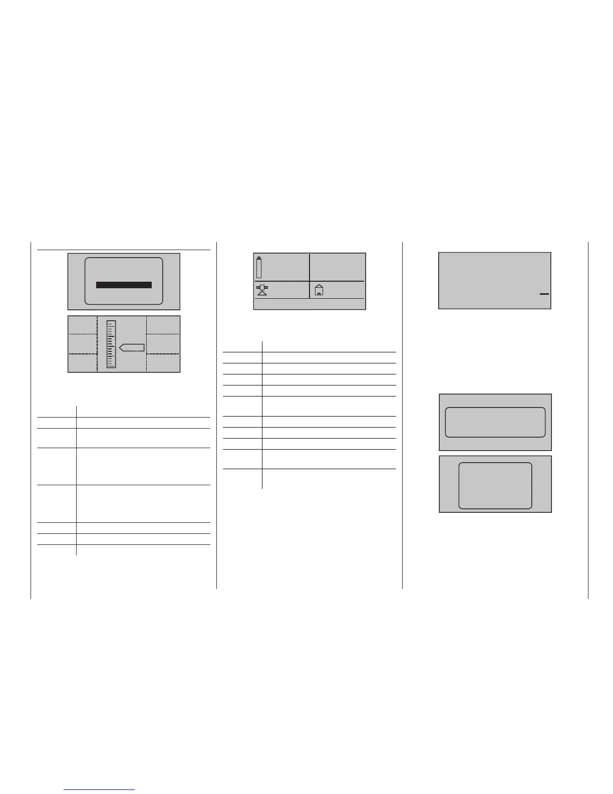
Text display
If the corresponding sensors are available, text from
them showing 2 x 10 or 3 x 7 characters can be super-
imposed in the two following displays when required:

 Loading...


