99
Program description - Model type | Winged models
Tail type
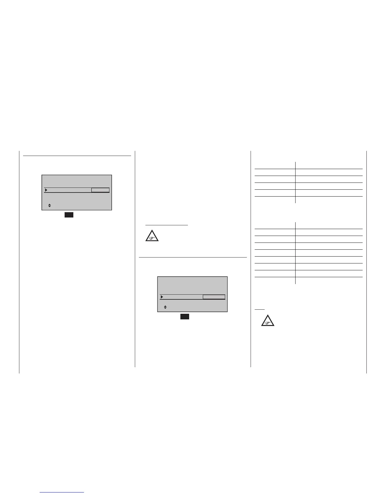
After selecting the “Tail type” line with the selec-
tion keys of the left or right four-way button, the corre-
sponding entry field will be framed.
+100%
SEL
Tail type
Motor at C1
Normal
None
Aile/flaps
1AIL
Model type
Brake Off In 1
Briefly tap the centre SET key of the right four-way
button: The current setting will be displayed in inverse
video. Now select the type appropriate for the model
with the selection keys of the right four-way button.
• “normal“
Elevators and rudder are each operated by a single
servo.
• “V-tail”
Elevator and rudder control is affected by way of
two separate, articulated, V-shaped rudders. The
coupling function for rudder and elevator control
will be automatically taken over by the program.
The relationship of rudder-to-elevator proportion is
set in the »Dual Rate / Expo« menu, page 126,
and servo travel in the »Servo adjustment« menu,
page 106.
If you also wish to apply differential to the rudder
travel, then an alternative method of controlling the
V-tail should be chosen. This requires the »Dual
mixer« menu – see page 214 – which is available
on the
mc-20 HoTT transmitter only. However, in
this case it is essential to set the tail type to “nor-
mal”.
• “Delta/”
If you choose “2 AIL” in the “Aile / flaps” line – see
below – then your model requires one servo in each
wing panel for aileron and elevator control.
If you choose “2/4 AIL 2/4 FL”, then aileron and ele-
vator are controlled in accordance with the settings
in the “Multi-flap” menu; see page 177.
• “2ELSv3+8”
This option is intended for models with two elevator
servos. The servo connected to output 8 will oper-
ate in parallel with servo 3 to actuate elevators. Ele-
vator trim affects both servos.
Note on “2ELSv3+8”:
One control, which assigns input 8 by way
of the »Control adjust« menu, is then
disconnected from servo “8” by software
for reasons of safety i. e. it is made ineffective.
Aileron/camber aps
After selecting the “Aileron/camber flaps” line with the
selection keys of the left or right four-way button,
the corresponding entry field will be framed:
+100%
SEL
Tail type
Motor at C1
Normal
None
Aile/flaps
1AIL
Model type
Brake Off In 1
Briefly tap the centre SET key of the right four-way
button: The current setting will be displayed in inverse
video. Now use the selection keys of the right four-way
button to select the number of wing servos to be pro-
grammed for the model …
… on the mc-16 transmitter with the standard eight
channels:
No. of wing flaps Control channel used
1AIL 2
1AIL 1FL 2 | 6
2AIL 2 & 5
2AIL 1FL 2 & 5 | 6
2AIL 2FL 2 & 5 | 6 & 7
… on the
mc-20 transmitter with twelve channels,
and the mc-16 transmitter with the optional twelve
channels:
No. of wing flaps Control channel used
1AIL 2
1AIL 1FL 2 | 6
2AIL 2 & 5
2AIL 1FL 2 & 5 | 6
2AIL 2FL 2 & 5 | 6 & 7
2AIL 4FL 2 & 5 | 6 & 7 / 9 & 10
4AIL 2FL 2 & 5 / 11 & 12 | 6 & 7
4AIL 4FL 2 & 5 / 11 & 12 | 6 & 7 / 9 & 10
Depending on the option selected here, the given mix-
ers needed and their settings will be activated in the
»Wing mixers« menu, beginning page 180.
Tips:
•
Settings for all wing ap pairs (AlL and
Al2, FL and FL2) can be trimmed on a
ight-phase basis in both the »Phase
trim« menu as well as in the Wing mixers«
menu, page 180.

 Loading...


