Automatic transmission-26
Power transmission
Introduction
It has the following power transmission pointed to different Gear-position:
power transmission N-Gear and P-Gear
power transmission R-Gear
power transmission manual 1
power transmission Automatic 1
st
-Gear
power transmission Automatic 2
nd
-Gear
power transmission Automatic 3
rd
-Gear
power transmission Automatic 3
rd
-Gear locking
power transmission Automatic 4
th
-Gear (overspeed -gear)
power transmission Automatic 4
th
-Gear locking
For description of each kind of power transmission condition, refer to following parts.
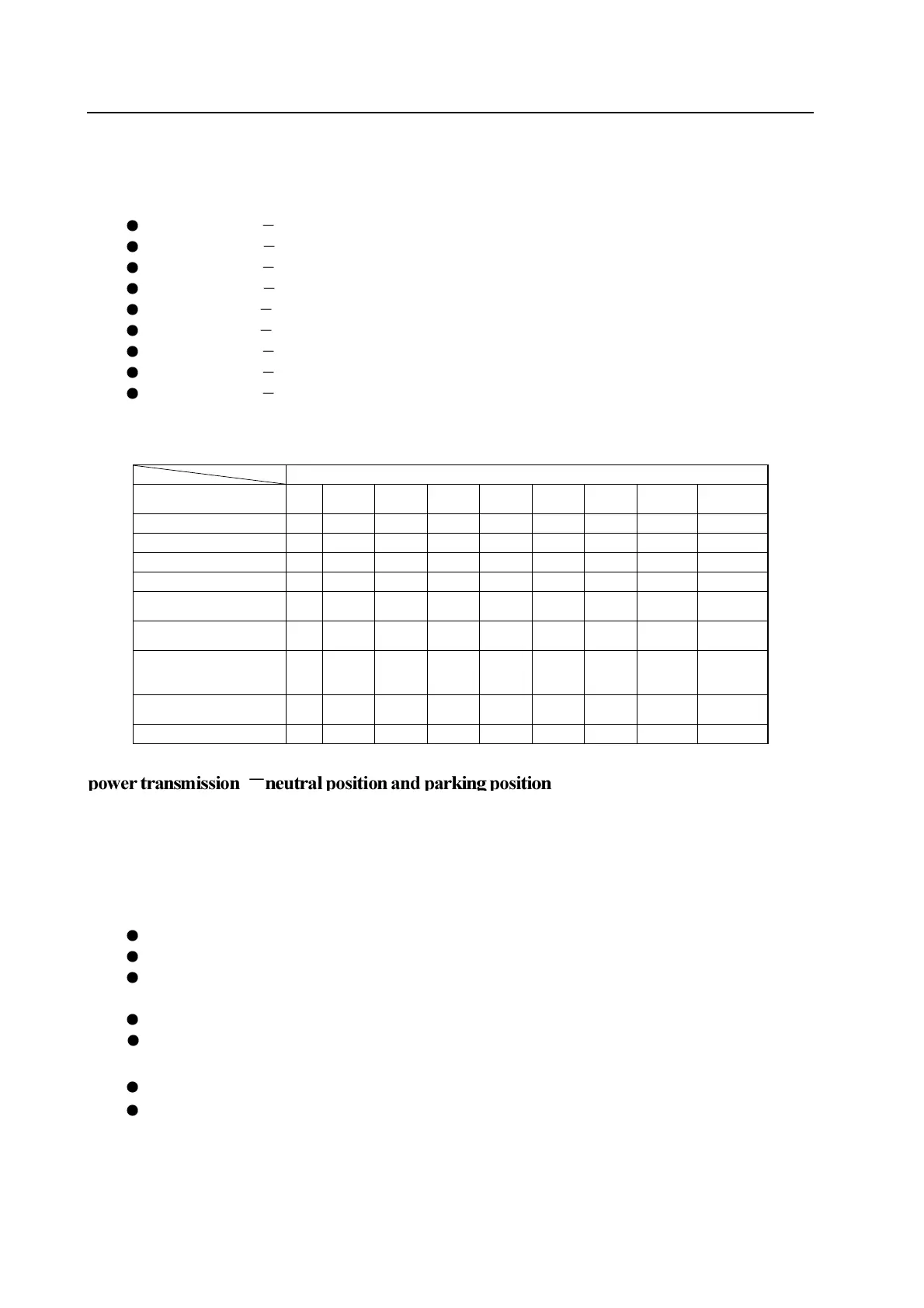
Table 5.1 describe the on-off condition of each unit in all gear condition.
Name of participated unit
Position C1 C2 C3 C4 B1 B2
1-2
OWC
3-4
OWC
LU
clutch
Parking and neutral position - - - - - X - - -
Reverse - - X - X - - -
Manual 1
st
-Gear - X - X - X - X
Automatic 1
st
- Gear - X - - - - X -
Auto 2
nd
-Gear and manual
2
nd
-Gear
- X - X X - - X -
Automatic 3
rd
–Gear and
manual 3
rd
-Gear
X X - X - - - X -
Automatic 3
rd
-Gear locking
and manual 3
rd
-Gear
locking
X X - X - - - X X
Automatic 4
th
-Gear
(overspeed -gear)
X X - - X - - - -
Automatic 4
th
-Gear locking
X X - - X - - - X
In P-Gear or N-Gear, the planetary gear assembly has not the drive. The rear brake belt is used to eliminate the voice generated in
engagement with reverse gear and increase the application of 4WD. It is without the engagement of clutch and brake belt.
In parking-Gear, the locking of mechanism is realized through the engagement of brake lever installed on housing and tooth of
output shaft gear ring.
Control
In stabl
e status, to maintain the arrangement, the status of solenoid valve and valve is shown as follows:
solenoid valve S1 and S2 is powered off.
The line (pump) pressure is applied on the primary regulating valve (PRV) and electromagnetic supply valve.
The torque converter, oil cooler and lubrication loop are filled up with the transmission fluid from the primary regulating
valve.
The line pressure 500 loop is filled up with the transmission fluid from the electromagnetic supply valve.
S5 will be filled up with the transmission fluid through the variable pressure
\regulating valve (S5) .
The line pressure is prohibited form entering into the drive loop through the manual-operated valve .
B1 loop and all clutch loop are opened to drainage port.