Automatic transmission-45
Diagnosis and test
Test system
1. Recommended test equipment and program
The test equipment and control unit for design will be used for the test of all vehicles. The parts for transmission test includes:
Tester for service after sales
Special vehicle for test
2. Tester for service after sales
After the special programming, the tester equipped with special car test software can be used to test the specified system and unit.
The program allows the normal communication between the transmission control units (TCUs) .
The computer needs the required information from the customer and select the necessary data through the manual. For example:
view the code, clear the error code and make the real-time operation. For detailed operating instruction refer to user’s manual.
The equipment can be used by the trained specialized persons, such as technician, machinist to test the electronic and loop
problem related to transmission. The testable information includes: the engine speed, rode (shaft speed), transmission fluid
temperature, position of throttle position, status of solenoid valve and gear and position of operating lever. Additionally, it can be
used to detect the current and stored problem.
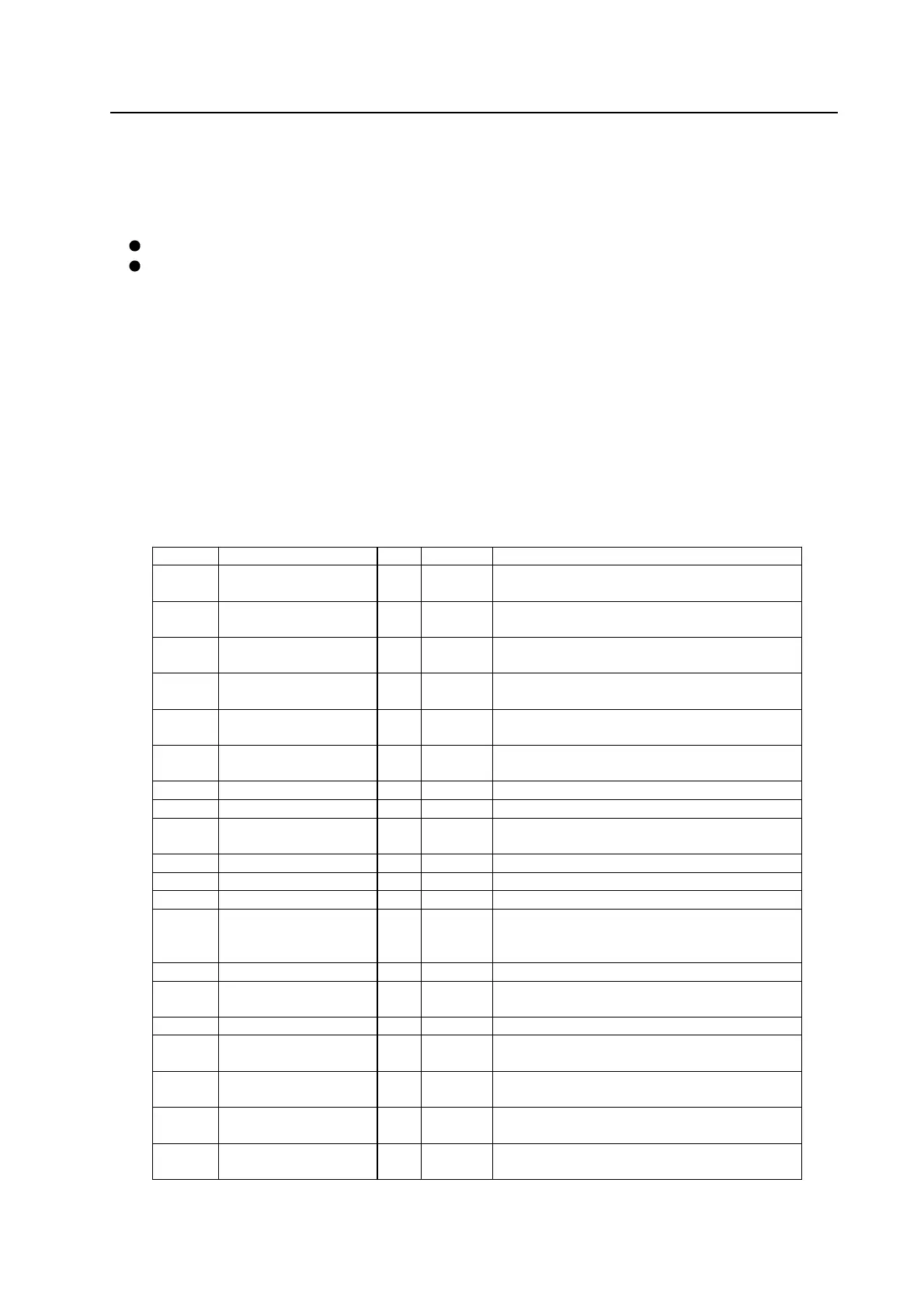
3. Description of TCU pin
The description of TCU pin code had been listed in Table 6.1.1
For description of wire bunch refer to Figure 6.1.1
Pin No. Function Type 2WD description
A14
Public grounding GND
●
Negative pole of TCU supply, connected to negative pole of
battery.
A13
Nonuse
--
○
-----
A12
Mode indicator lamp
Snowland mode
OP
●
Indicate that select the “Snowland Mode” operating method.
A11
Parking-Gear indicator lamp OP
●
The drive instrument panel indicator lamp indicates that is in
the “Parking Gear”
A10
Reverse-Gear indicator lamp OP
●
The drive instrument panel indicator lamp indicates that is in
“Reverse Gear”
A9
N-Gear indicator lamp OP
●
The drive instrument panel indicator lamp indicates that is in
“Idle N Gear”
A8 Nonuse -- ○ -----
A7 Nonuse -- ○ -----
A6
Mode indicator lamp
dynamic mode
OP
●
Indicate that select the “dynamic mode” operating method.
A5 Nonuse ―― ○ ---――
A4 Nonuse ―― ○ -----
A3 Nonuse ―― ○ -----
A2
Mode switch IP
●
The switch is used to select the “economic mode”, “dynamic
mode” and “snowland mode”. The voltage is variable in
range of 0 V-2V .
A1 Nonuse ―― ○ -----
A30
Power supply PWR
●
Power supply for TCU; is the main power source of drive
unit and solenoid valve.
A29 Nonuse ―― ○ -----
A28
1
st
-Gear indicator lamp
/1
st
-Gear position﹡
OP
●
Drive the instrument panel indicator lamp indication, indicate
that the gear-position is in “1
st
-Gear”
A27
2nd-Gear indicator lamp
/2nd-Gear position
OP
●
Drive the instrument panel indicator lamp indication, indicate
that the gear-position is in “2
nd
-Gear”
A26
3
rd
-Gear indicator lamp
/3
rd
-Gear position﹡
OP
●
Drive the instrument panel indicator lamp indication, indicate
that the gear-position is in “3
rd
-Gear”
A25
Automatic gear indicator
lamp /4
th
–Gear position
OP
●
Drive the instrument panel indicator lamp indication, indicate
that the gear-position is in “automatic-Gear”