12. Clutch C1 overspeed shaft and input shaft assembly
Caution:
a. Ensure the correct installation of snap ring.
b. Check the piston for crack.
c. Must not mix the clutch piston out and back spring.
d. If the connector of clutch C1/ C2 is disconnected form the clutch C3, ensure the NO.6 bearing can not slide down
from the bearing retainer.
The installation procedure of clutch C1 overspeed shaft and input shaft assembly is as follows:
a. Check the overspeed shaft groove for damage.
b. Coat the big and small sealing ring with the Vaseline and install it on the overspeed shaft. It can use few Vaseline to fix the
sealing ring on its correct position.
c. Install the clutch disk and other disc on the cylinder according to the following sequence:
steel plate
abrasion plate
steel plate
abrasion plate
steel plate
steel plate
steel plate (optional)
friction disk
steel plate (optional)
friction disk
Caution:
The clutch assembly can support the weight of 19.6N; the distance form the fixing point of input shaft to the friction disk
is 0.70
0.90mm.
Caution:
It should take out the clutch assembly before immerse the assembly in the transmission fluid.
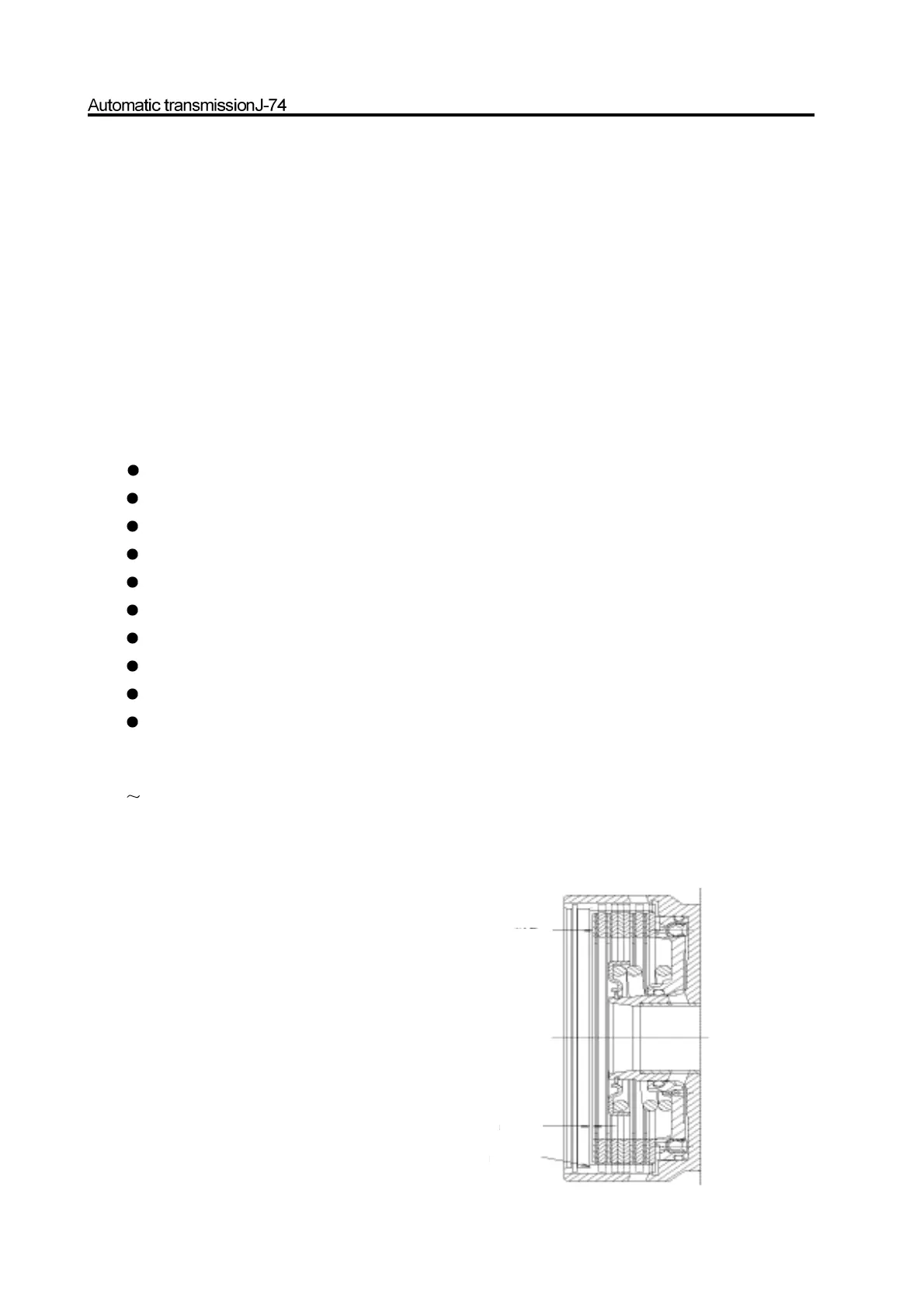
d. Use the tools to check the clutch assembly clearance. Refer to Figure 8.31. Use the proper selected disc plate to acquire the
correct required clearance.
Figure 8.31 clutch C1 assembly clearance
clutch C1
19.6N load
input shaft position
clutch clearance0.7-0.9mm0.7-0.9mm