Automatic transmission-37
power transmission Automatic 3
rd
-Gear and manual 3
rd
-Gear
In automatic and manual 3
rd
-Gear, the drive of transmission reaches the front cylinder through the input shaft. In this condition,
the operating principle of the transmission is shown as follows:
The engagement of clutch C2 drives the front sun gear
The engagement of clutch C1 drives the planetary gear carrier
The forward central gear and planetary gear carrier rotate in the same speed clockwise. So, there is not relative motion
between the forward central gear and planetary gear.
The gear ring and output shaft rotate in the speed of output shaft, and makes the moves forwardly.
The engagement of clutch C4 is through the 3-4 one-way clutch (OWC) and make the engine to provide the brake force
in overspeed.
Control:
In stable status, the status of solenoid valve and valve is shown as follows:
The solenoid valve S1 is powered off; Solenoid valve S2 is powered off
When the solenoid valve S1 and S2 is powered off, 2-3 and 3-4 shift valve are kept in 3
rd
-Gear position through the line
pressure 500.
1-2 Gear shifting valve is kept in 3
rd
-Gear position by the oil pressure of S1 and S2.
The (line pressure)oil form the 1-2 Gear shifting valve flows into the brake belt combination regulating valve directly and
flows into the 2-3 Gear shifting valve.
The brake belt combination regulating valve provides the 2
nd
-Gear oil (controlled by the product of line pressure and valve)
to the brake belt feed loop(BAF).
The brake belt feed loop directly provides the oil to:
External combination part of front servo
When the transmission is shifted to 1
st
-Gear, the 1-2 Gear shifting valve provides the oil drainage port.
When the transmission is in 4
th
–Gear position, it will use the 3-4 Gear shifting valve.
The 2
nd
-Gear oil of 2-3 Gear shifting valve flows into the 3
rd
-gear loop directly .
The 3
rd
-Gear oil from the 2-3 Gear shifting valve flows into the clutch combination regulating valve and sequence valve of
4-3 Gear directly.
The clutch combination regulating valve provides the oil of clutch attachment feed loop (controlled by the product of line
pressure of 500 and valve ratio) (CAF).
CAF directly provides the oil to :
clutch C1
Sequence valve of 4-3 Gear
In 4-3 Gear shifting valve, the CAF oil is changed to the release fluid of B1 (B1R-F), it cause the closing of brake belt 1
through the 3-4 Gear shifting valve to spring bottom of 4-3 gear sequence valve and release side of front servo.
The drive force (line pressure ) is sent to the clutch C4 through the 3-4 Gear shifting valve to engage the clutch C4 .
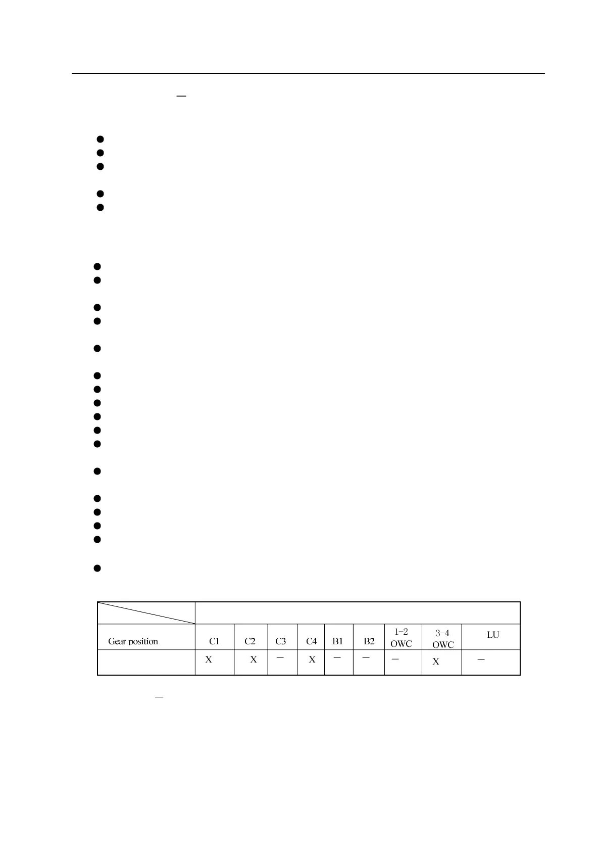
Refer to Figure 5.6 and Table 5.7.
Table 5.7
Table of participating condition of each unit in automatic and manual 3
rd
–Gear
Clutch
Name of participation unit
Automatic and manual
3
rd
–Gear