Automatic transmission-7
Indicator lamp
Figure 2.2
control system
General
The transmission has two sets of control system, a electric control system and a hydraulic control system. The electric control
system monitors the vehicle parameter and adjusts the transmission performance; the hydraulic control system executes the
command of electric control system.
Electric control system
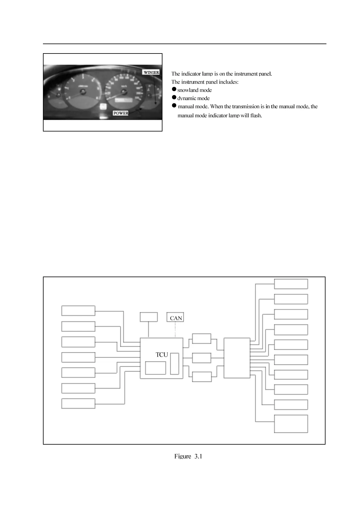
The electric control system consists of the sensor, TCU and 7 solenoid valves. TCU read in the data and make the output under the
control of software based on the value stored in Read Only Memory (ROM).
TCU controls the hydraulic control system and the control is realized through the valve and pump assembly. The system includes
7 solenoid valves, in which 6 valves are used to control the line pressure, operate the shift valve and hydraulic torque converter lock
clutch and switch on and off two regulating valves (Two regulating valves control the shift feel). The seventh solenoid valve is the
pressure regulating solenoid valve (VPS) which controls the shift feel with other three regulating valves. Figure 3.1 is the typical TCU
control system plan.
The figure includes all elements of electric control system involved in the section.
throttle position
open sensor
Engine speed
vehicle speed
Transmission
fluid temperature
mode selection
(instrument panel
/console )
Gear sensor
Forced step-
decreasing
K line
shifting
logic
shifting
sensing
line
pressure
hydraulic
control
system
Solenoid valve 1
Solenoid valve 2
Solenoid valve 3
Solenoid valve 4
Solenoid valve 5
Solenoid valve 6
Solenoid valve 7
pressure regulating
solenoid valve
Mode indicator lamp
Gear indicator lamp
set and other
necessary equipment
indication