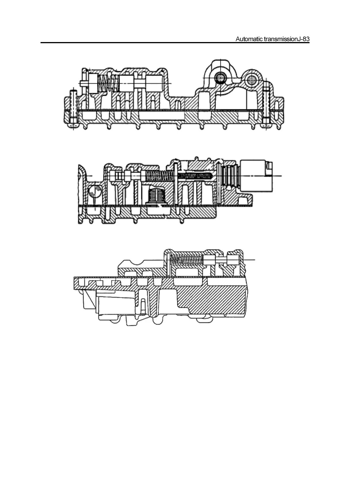
Figure 8.53 clutch combination regulating valve and solenoid 3
Figure 8.54 solenoid combination valve and solenoid 6
Figure 8.55 reverse lock valve
j. Position the 3
rd
feed ball (large nylon ) on the valve and solenoid supply valve filter, shown as Figure 8.54.
k. Check the separating disk for abrasion, repair or replace if necessary.
l. Check the washer of upper and lower valve for damage, replace it if necessary
m. Install the upper shim of lower position valve.
n. Install the reverse lock valve, spring and fixed disc; ensure the correct installation of valve; shown as Figure 8.55.
o. Install 5 nylon balls on the upper valve, shown as Figure 8.46. Install the upper valve shim; install the separating disk on the
upper valve.
p. Lift the separating disk to the upper valve; prevent the detection ball from falling ; install the upper valve on the low pressure
valve. Tighten all screws. Refer to Figure 8.56.