Automatic transmission-19
Figure 3.15 clutch combination regulating valve
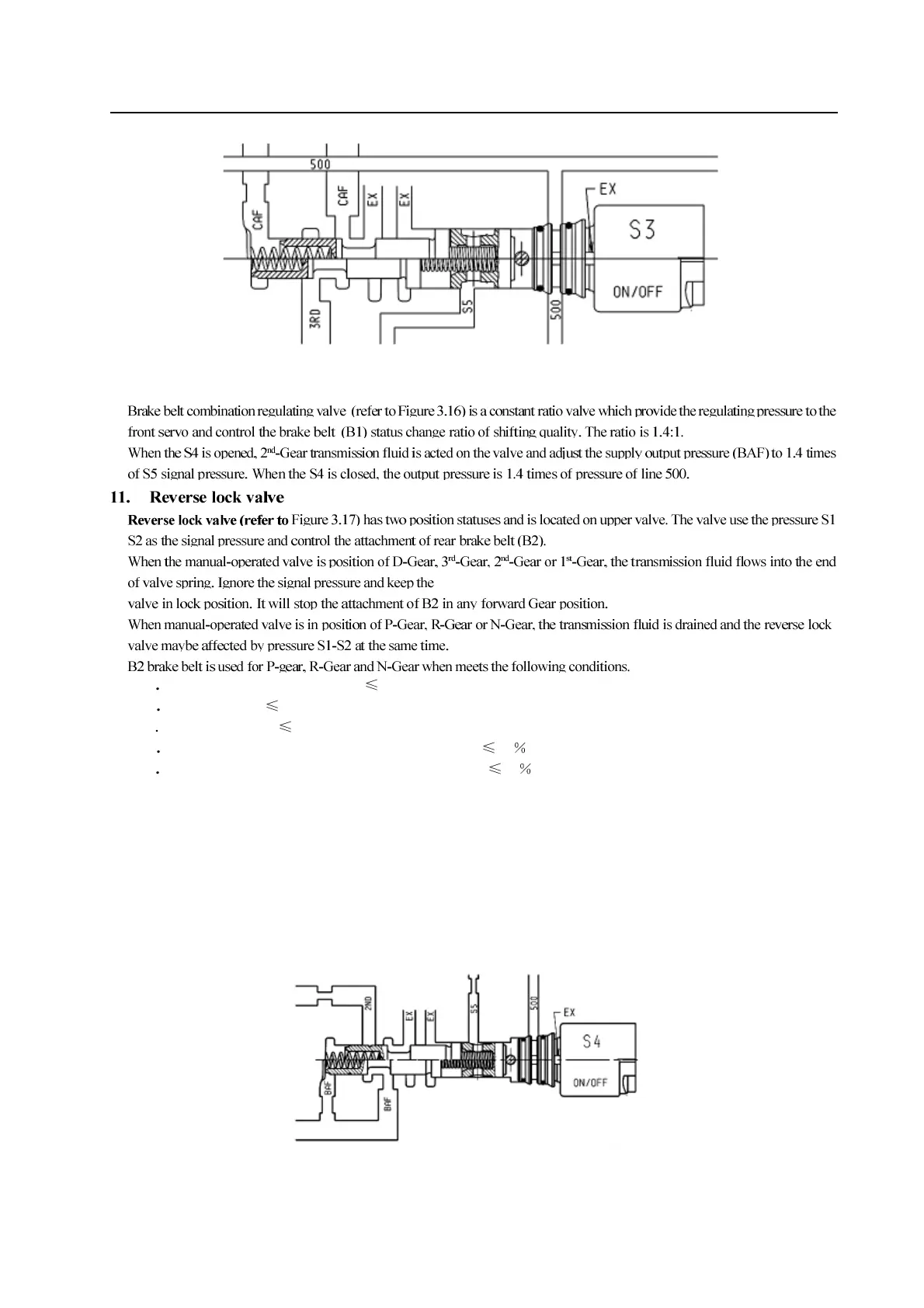
10. Brake belt combination regulating valve
a P-Gear or N-Gear, vehicle speed 3km/h
b
R-Gear , speed 10km/h
c
Speed of engine : 1250rpm
d
Diesel vehicle , Opening degree of throttle position: 25
e Gasoline vehicle, opening degree of throttle position: 12
In this condition, the TCU control solenoid valve S1 and S2 are closed. The reverse lock valve is affected by the pressure form
S1-S2 transmission fluid; connect the line pressure to loop B2. The transmission fluid flows to servo internal and external
attachment area, the B2 is engaged.
When none of above condition is met, TCU control the solenoid valve S1 and S2 to be opened. The pressure of S1-S2 is
released and the spring control valve body is in locking status at the same. In this condition, the B2 attachment is prohibited.
The feature can realize the protection for transmission by controlling the B2 in high speed and providing the reverse-gear
locking.
If the transmission is in failure mode, then the rear brake belt will be attached in P-Gear, R-Gear and N-Gear.
Figure 3.16 brake belt combination regulating valve