Automatic transmission-10
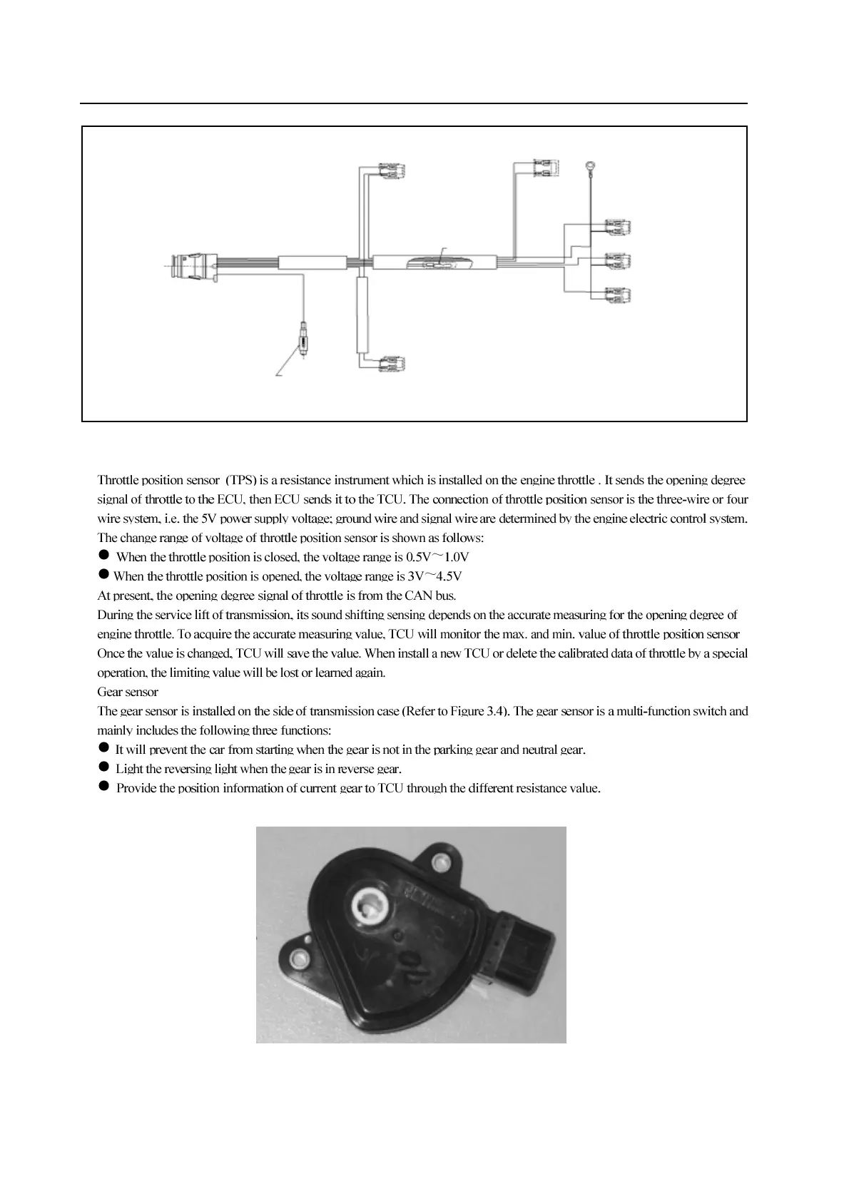
Figure 3.3 Schematic diagram of temperature sensor position and solenoid valve wiring
2.Throttle position sensor
Figure 3.4 gear sensor
solenoid valve 4 (orange )
ground wire (2)
solenoid valve 7 power supply connector
olenoid valve 6 (violet )
ground wire
temperature sensor
solenoid valve (red )
ground wire
solenoid
valve (green )
solenoid valve (yellow )
solenoid valve (blue )
ground wire
ground wire
ground wire