Automatic transmission-35
Power transmission automatic 2
nd
-Gear and manual 2
In automatic 1
st
and manual 2
nd
-Gear, the drive of transmission reaches the front clutch cylinder through the input shaft. In this
condition, the operating principle of each functional unit of transmission is shown as follows:
The engagement of clutch C2 drives the forward central gear.
The forward central gear drives the short planetary gear to rotate in anticlockwise.
The short planetary gear drives the long planetary gear to rotate clockwise.
The engagement of brake belt B1 makes the stop of reverse central gear to make the long planetary gear rotates around the
reverse central gear, then make the internal gear and output shaft rotates in clockwise to make the vehicle moves forwardly.
The clutch C4 is engaged through the 3-4 one-way clutch (OWC) and provides the brake force of engine during overspeed.
Control:
In stable status, the status action of solenoid valve and valve is shown as follows:
The solenoid valve S1 is powered off ; The solenoid valve S2 is powered on.
The drive oil (line pressure) from the manual-operated valve makes the engagement of clutch C2.
When the solenoid valve S1 is powered off, the S1 oil pressure form line pressure 500 pushes the 3-4 Gear shifting valve
moves to left. At the same time, the S1 oil flows into the 1-2 Gear shifting valve to push the 1-2 Gear shifting valve to the
2
nd
–Gear.
The line pressure oil from the 1-2 Gear shifting valve flows into the brake belt combination regulating valve, and 2-3 Gar
shifting valve.
The brake belt engagement regulator valve provides the 2
nd
-Gear oil (controlled by product of line pressure and valve rate)
to brake belt feed loop (BAF).
The brake belt engagement feed loop directly provides the oil to:
External engagement part of front servo piston.
1-2 Gear shifting valve can provide a oil drainage port when the transmission is shifted to 1
st
-Gear.
Use the 3-4 Gear shifting valve when the transmission is in 4
th
-Gear position.
The drive force (line pressure) is sent to the clutch C4 through the 3-4 Gear shifting valve to realize the engagement of
clutch C4.
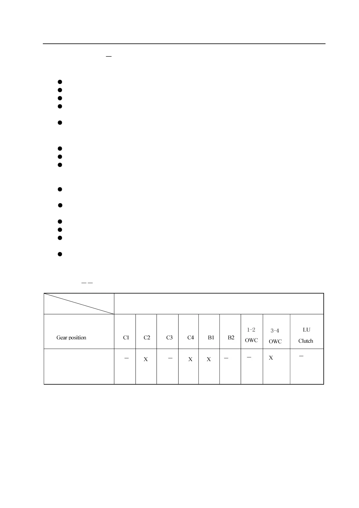
Refer to Figure 5.5 and table 5.6
Table 5.6 The participating condition of each unit in automatic 2
nd
-Gear and manual 2
nd
-Gear
Automatic 2
nd
-Gear and manual
2
nd
-Gear
Name of participation unit