Figure 8.11 Rear servo bar
Caution:
Pay attention to do not coat the sealant between the bolt and crown bar.
e. Install the parking operating lever (as Figure 8.12), including the return spring and shaft pin. Coat the external end of shaft pin
with small sealant.
f. Use the circlip to protect the shaft pin. Pay attention to ensure the operating lever can rotate around the shaft pin freely and
the spring can make the parking operating lever returns to the correct position.
g. Install the parking brake lever pin and spring. Refer to Figure 8.13.Caution: ensure the rake lever can rotate freely.
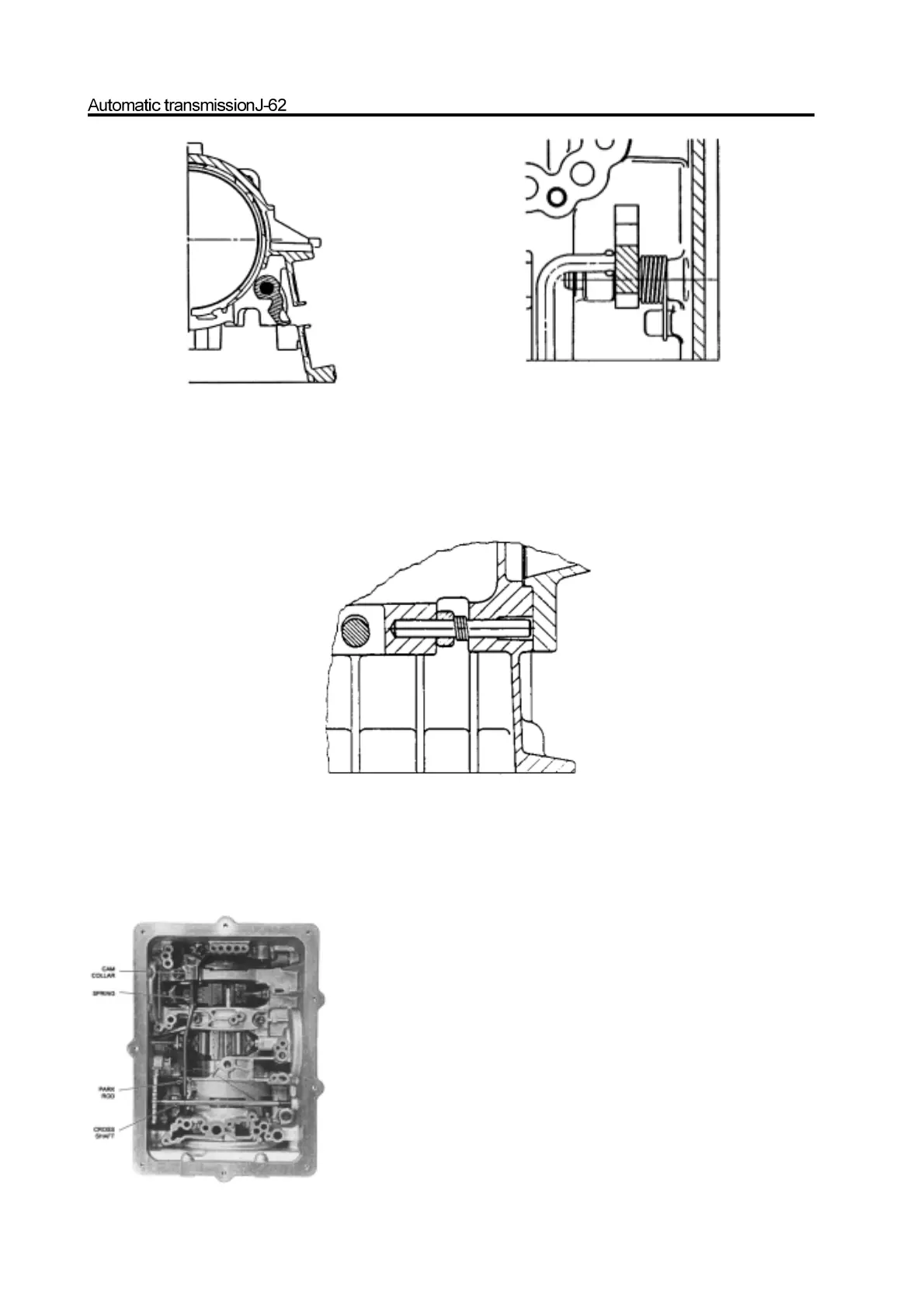
h. Connect the parking brake lever to the manual-operated valve connecting rod. Shown as Figure 8.14. Ensure the spring and cam
axle ring are installed on the connecting rod fixedly.
i. Check the cam axle ring for smooth sliding on rod.
j. Install the cross shaft in the box in reverse direction of Gear-position sensor, then install the concussion spring on the shaft.
Figure 8.12 Parking operating lever
Figure 8.13 Typical parking brake shaft pin and spring
Figure 8.14 Parking lever and manual shaft