Automatic transmission-22
Power transmission system
The power transmission system includes:
Torque converter equipped with single lock clutch.
4 multi-plate clutch assemblies
2 brake belts
2 one-way clutches
Planetary gear assembly
parking mechanism
A traditional planetary gear assembly composed by six pinions is used in four-speed transmission. It realizes the 4 Gear power
transmission through the drive gear bracket.
So, the cross arrangement is the main arranging method. In the box, there are four subassemblies, shown as follows:
Gear bank central support
C1-C2-C3-clutch C4 subassembly
Pump assembly
Valve assembly
One piece or one set of optional shim is located between the input shaft flange and center of stator support shaft axle of and used
to control the end flotation of transmission. The structure arrangement allows the inspection for the subassembly during the
product manufacturing period.
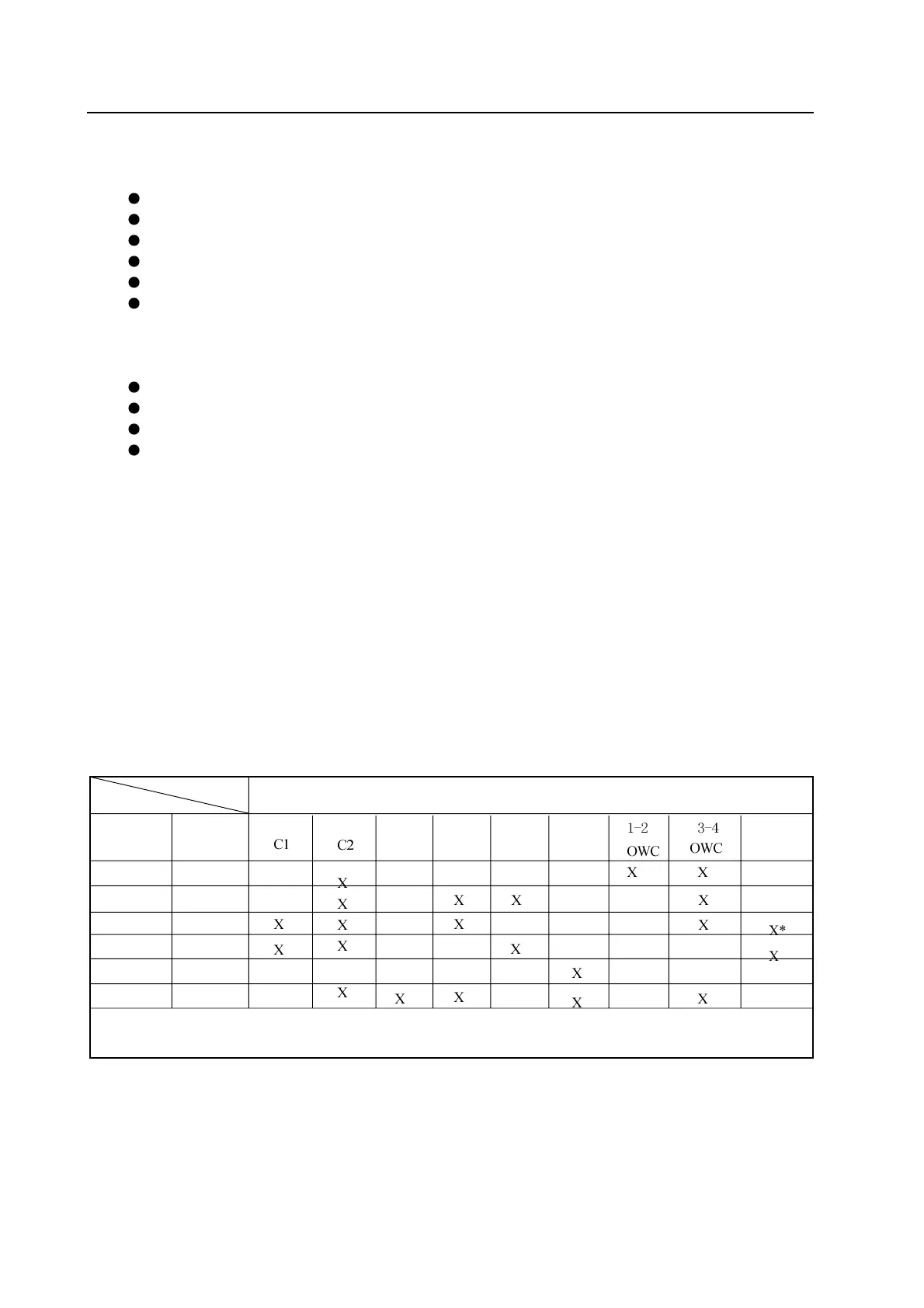
For description of power transmission system refer to table 4.1 and Figure 4.1:
When the clutch C2 is engaged and 1-2 one-way clutch is engaged, the gear is in 2nd-Gear at this time. During the 1-2 shifting
process, B1 brake belt is combined and the 1-2 one-way clutch is separated (OWC). During the 2-3 shifting period, the clutch
C1 is engaged and the B1brake belt is released. During the 3-4 shifting period, B1brake belt is engaged and 3-4 one-way clutch
is released. For reverse gear, the clutch C3 and B2brake belt is engaged.
When the gear position is in manual 1st, 2
nd
and 3
rd
gear position, the engagement of the clutch C4 can provide the brake of
engine. Additionally, in the drive scope of 2
nd
and 3
rd
Gear, the engagement of clutch C4 can eliminate the unfavorable freewheel
inertia. In the scope of manual 1
st
-Gear, the low speed shifting is realized by the engagement of B2brake belt.
The front and rear servo has the figure surface design which requires the accurate friction and need not the secondary regulating
valve. When use the transmission fluid with new static factor, the design of the friction unit can meet the requirement that need
low shifting energy and high static holding force. The transmission uses the non-asbestos friction material.
LU
Gear position Gear ratio
1st-Gear 2.393
2
nd
-Gear 1.450
3
rd
-Gear 1.000
4
th
-Gear 0.677
R-Gear 2.093
Manual 1 2.393
C3
C4 B1 B2
Name of participated unit
* For operation of specified vehicle refer to user’operation manual.
LU: hydraulic torque converter lock clutch
Table 4.1 Participated unit and gear ratio in different gear position