e. If need to install the new friction disk, please remove the clutch assembly and immerse the friction assembly into the
transmission fluid for 5 minutes at least before the installation.
f. Check whether the clutch C1 wheel axle is matched with the overspeed shaft. It should replace the wheel axle and wheel axle
assembly if loose.
g. Coat the small nylon thrust insulation plate with the Vaseline and installs it on the overspeed shaft. Refer to Figure 8.19.
h. It should be carefully when install the overspeed shaft on the C1 cylinder to avoid the damage of sealing ring.
i. Use the Vaseline to install the small copper C1 wheel axle thrust washer, shown as Figure 8.19.
j. Check the input shaft for problem. Install the input shaft on the cylinder and use the ring spring to install the wire safety of
input shaft and cylinder. Ensure the coil is in groove completely.
k. Use the petroleum jelly to install the gasket and place it on the input shaft.
l. Assemble the C1/C2/C4 clutch, clutch C3 and sun gear, shown as figure 8.24, 8.32
m. Install the assembly in the transmission case.
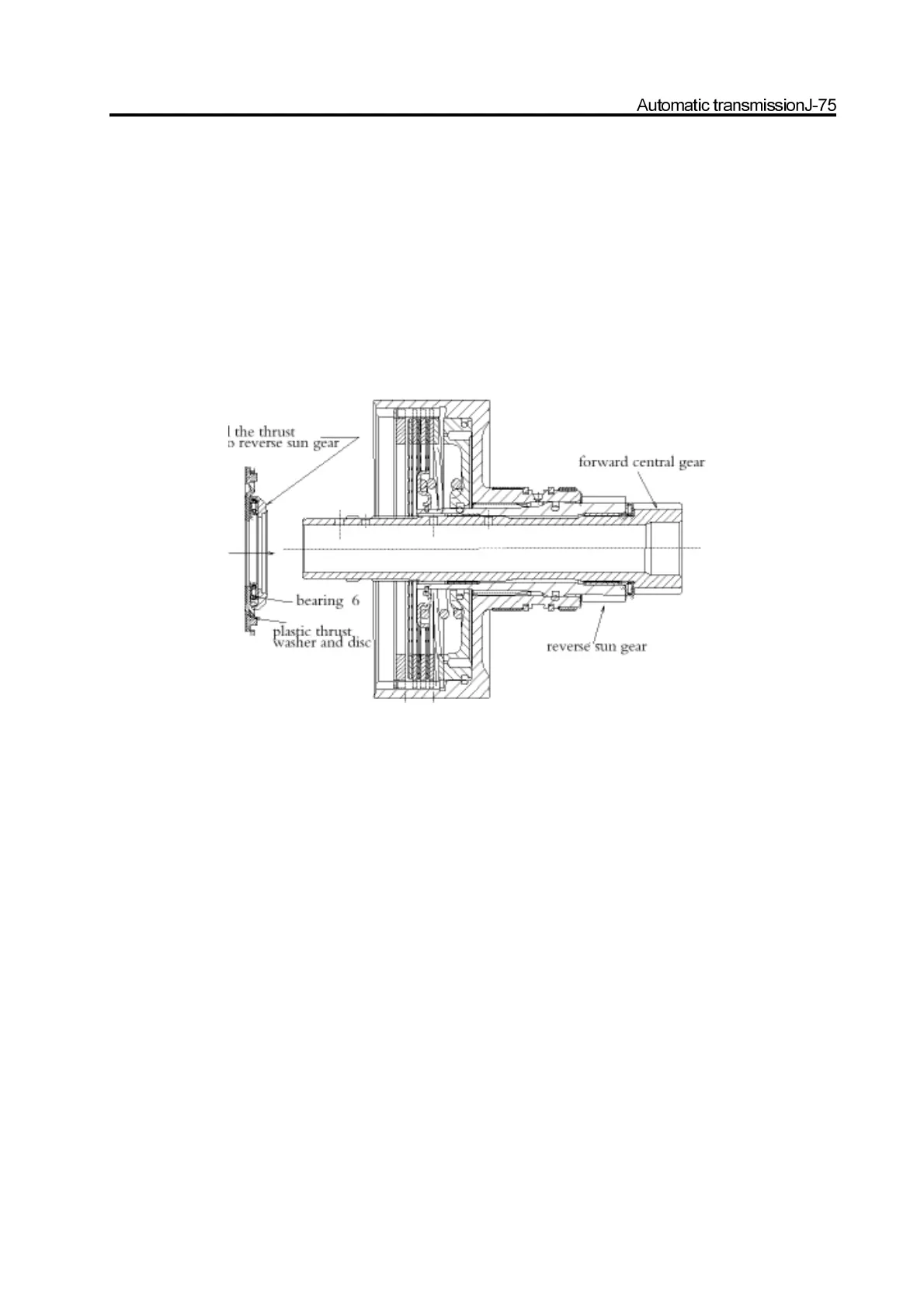
Figure 8.32 and 8.33 assembly number: 6 bearing and pressure disc to clutch C3 assembly
13. Pump housing and torque support
Caution:
a. Do not clean the solenoid valve by solvent.
b. Ensure the O-ring is installed in the correct position.
c. Do not blow off the first drop and mix it with the ball spring blowed off by the torque converter. ( only for the condition of
installing the transmission to STD pump housing)
d. Do not damage the line bearing on the assembly; avoid any impact for bearing during the loading.
e. Check the end floating of transmission; it is help for the lose and incorrect assembly of any assembly.
Caution: Figure 8.35 The orientation of crossing part is shown in Figure 8.36 to 8.42.
The assembly procedure of pump housing and torque converter is as follows:
a. Check the pump for damage, chip and abnormity; check whether the sleeve of drive gear is fixed.
b. Wash the pump and pump gear carefully; remove all redundant oil and dirt.
c. Install the pump gear and pump. Use the micrometer to measure the depth from the surface of pump to gear surface. The
measured value is the side clearance of pump. The side clearance should be in the range of 0.020-0.040mm.
d. Remove the pump gear from the pump.
e. If had been removed, please replace the pump sealing. Ensure the cleanness of pump sealing.
f. Use the transmission liquid to lubricate the pump gear, pump, washer and sealing and install the pump gear on the pump.