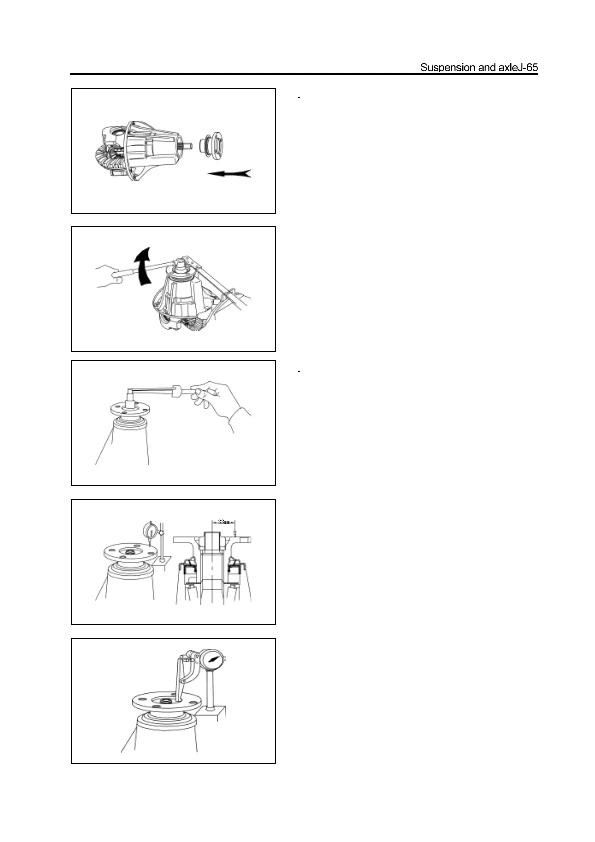
8 Install the drive gear flange and dustproof cover
assembly
a. Match the drive gear flange and dustproof cover assembly on
the front drive gear.
b. Coat the new nut with the lithium base grease.
c. Use the special tools to clamp the flange and tighten the nut
to the specified torque.
Tighten torque:140-160N.m
a. Use the torque meter to measure the pre-applied load of the
gap between the drive bevel gear and driven bevel gear.
pre-applied load: 1.2-1.7N.m
b. Is should be replaced by the thicker washer if the pre-ap
plied load is more than specified value
(The step of thickness of washer is 0.03mm)
c. Is should be replaced by the thinner washer if the pre-applied
load is less than specified value. Repeat the previous
operation until meet the requirement.
Caution: Do not reduce the load by loosing the nut.
10. Check the axial and radial run-out tolerance
offlange.
a. Use the dial indicator to measure the axial runout of flange.
Max. axial runout: 0.1mm
b. The max. radial run-out tolerance is 0.1mm
It should check the bearing if the radial run-out tolerance is large.
9 Adjust the pre-applied load of the drive
bevelgear bearing