20. Check the engaging mark of drive and driven
bevel gear.
(Refer to “Assembly of Front Reducer Assembly”)
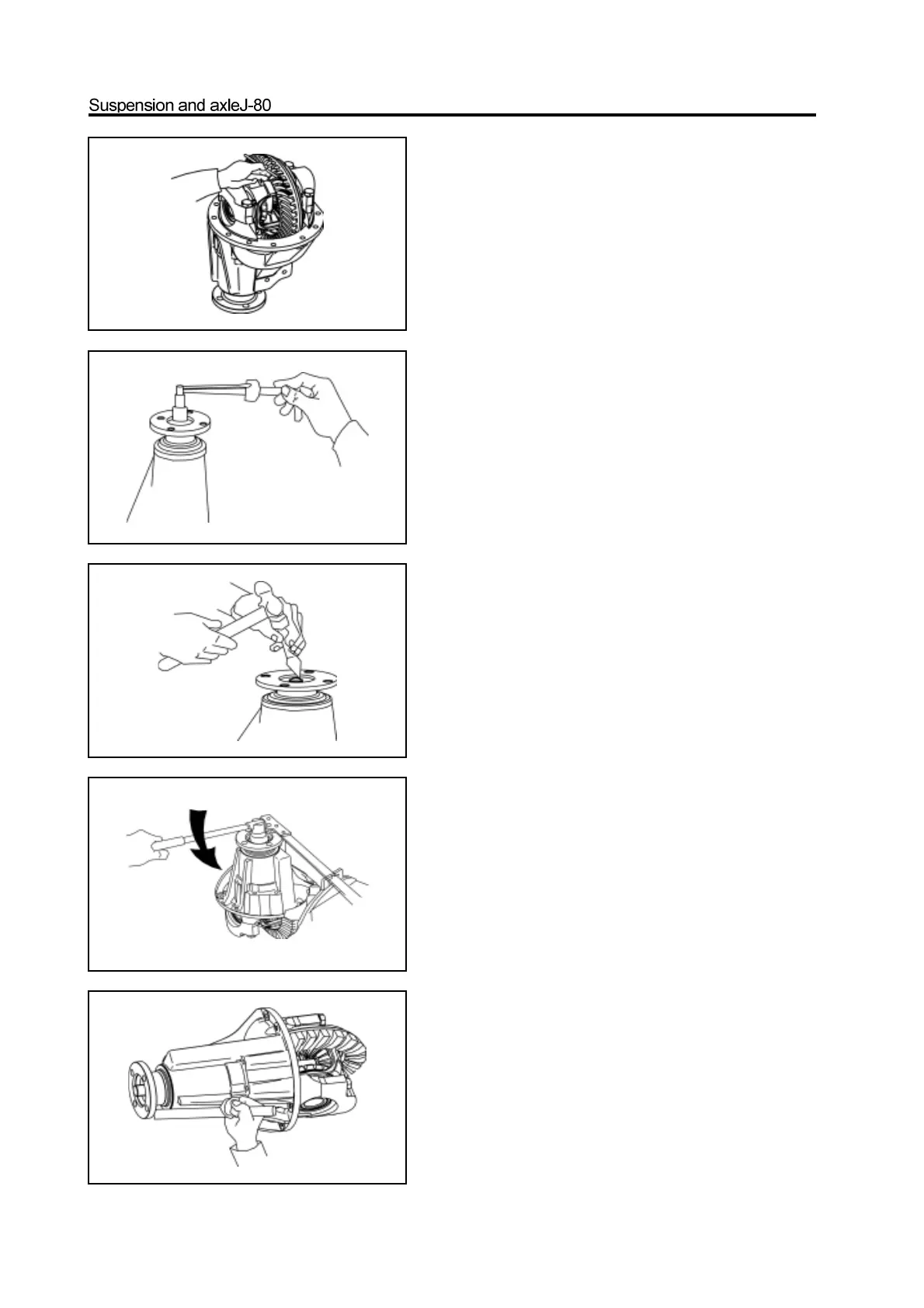
21. Measure the pre-applied load of drive bevel gear
bearing.
Use the torque measuring meter to measure the preapplied
load on the gap between the drive and drivenbevel gear.
Range of pre-applied load: 1.2-1.7N.m
22. Measure the total pre-applied load of drive bevel
gear.
23 Remove the drive gear flange and dustproof cover
assembly.
a. Use the hand hammer and chisel to loose the riveted part of
drive gear nut.
b. Use the special tools to clamp the drive gear flange and
remove the drive gear nut.
c. Use the brass rod to knock down the drive gear flange and
dustproof cover assembly.