1-12
During MSTP calculation, a boundary port’s role on an MSTI is consistent with its role on the CIST. But
that is not true with master ports. A master port on MSTIs is a root port on the CIST.
11) Roles of ports
MSTP calculation involves these port roles: root port, designated port, master port, alternate port,
backup port, and so on.
z Root port: a port responsible for forwarding data to the root bridge.
z Designated port: a port responsible for forwarding data to the downstream network segment or
device.
z Master port: A port on the shortest path from the current region to the common root bridge,
connecting the MST region to the common root bridge. If the region is seen as a node, the master
port is the root port of the region on the CST. The master port is a root port on IST/CIST and still a
master port on the other MSTIs.
z Alternate port: The standby port for the root port and the master port. When the root port or master
port is blocked, the alternate port becomes the new root port or master port.
z Backup port: The backup port of a designated port. When the designated port is blocked, the
backup port becomes a new designated port and starts forwarding data without delay. A loop
occurs when two ports of the same MSTP device are interconnected. Therefore, the device will
block either of the two ports, and the backup port is that port to be blocked.
A port can play different roles in different MSTIs.
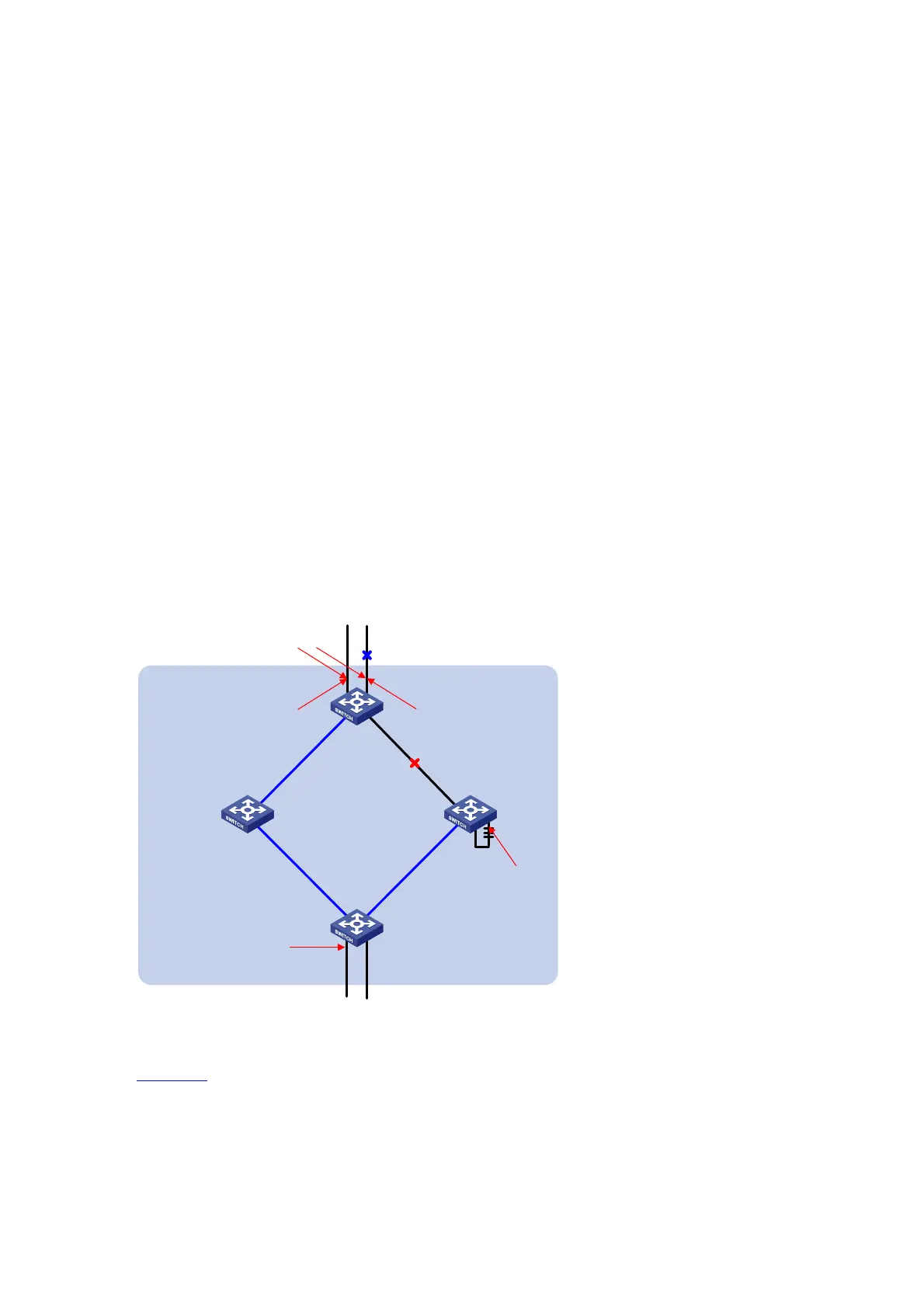
Figure 1-5 Port roles
Connecting to the
common root bridge
Boundary port
Port 1
Port 2
Master port Alternate port
Designated port
Port 3Port 4
Port 5
A
B
C
D
Port 6
Backup port
MST region
Figure 1-5 helps understand these concepts. In this figure:
z Devices A, B, C, and D constitute an MST region.
z Port 1 and port 2 of device A connect to the common root bridge.
z Port 5 and port 6 of device C form a loop.
z Port 3 and port 4 of device D connect downstream to other MST regions.
12) Port states

 Loading...


