104
_____________________________________________________________________________________________
6.6 PASS or FAIL Determination
______________________________________________________________________________________________
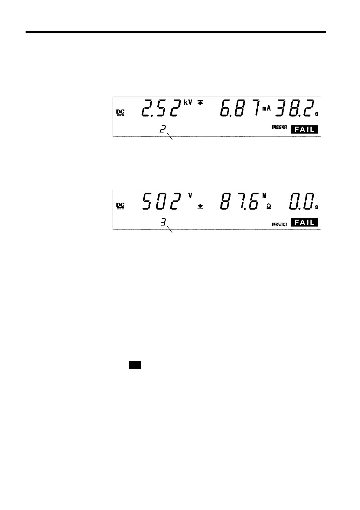
6.6.4 Screening in "FAIL" State
Step number
Step number
(1) When performing a withstand-voltage test:
Similar to the withstand-voltage mode FAIL state. (See Section 3.5.3)
(2) When performing an insulation-resistance test:
Similar to the insulation-resistance mode FAIL state. (See Section 4.5.3)
Danger lamp
Indicates that a voltage is being output. The lamp stays on during the test.
The lamp will also light if a voltage exceeding the safety voltage
(approximately AC 0.03 kV (AC withstand-voltage test)) or approximately
DC 60 V (DC withstand-voltage test or insulation-resistance test) remains
between the output terminals after the test has been completed.
Analog voltmeter
Indicates the voltage value being output. Even when values are held using
the "FAIL hold function," the value of the analog voltmeter is not held.
External I/O
As soon as
FAIL
on the fluorescent indicator lights up, the
L-FAIL
――――――――――
or
U-FAIL
――――――――――
signal lights up. At the same time, the
FILE-END
―――――――――――――
signal also lights
up for 0.1 seconds. While the FAIL state is held, both
L-FAIL
――――――――――
and
U-FAIL
――――――――――
signals remain ON. As soon as FAIL on the fluorescent indicator goes off,
the
L-FAIL
――――――――――
or
U-FAIL
――――――――――
signal goes off.
As soon as FAIL on the fluorescent indicator lights up, the
W-FAIL
―――――――――――
signal
(in the case of a withstand-voltage test) or
I-FAIL
―――――――――
signal (in the case of an
insulation-resistance test) lights up.
If voltage remains in the output-voltage terminal following termination of a
test, the
H.V.ON
――――――――――
signal remains ON. When the
DANGER
lamp goes out,
H.V.ON
――――――――――
signal is immediately turned OFF.