70
_____________________________________________________________________________________________
5.2 Displaying the "READY" State
______________________________________________________________________________________________
SHIFT
+
STOP
Displays the Optional functions setting screen.
(See Chapter 7)
START
Test Start (See Section 5.4)
LOCK
Key-lock function (See Section 5.2.1)
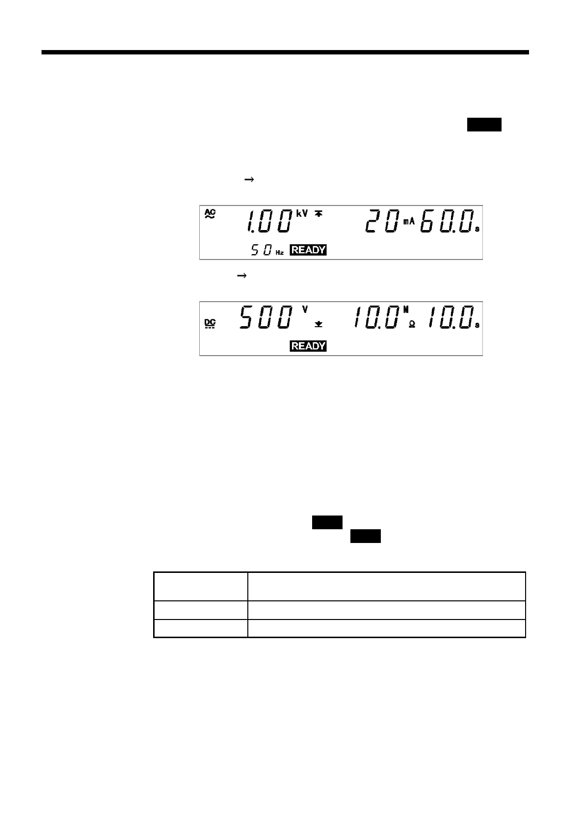
5.2 Displaying the "READY" State
In the READY state, the unit is always ready to start a test. The
READY
lamp remains lit to indicate the READY state.
You can make settings for each test type in a variety of modes. (See chapter
3andchapter4)
The settings for W I mode are the same as those for withstand-voltage
mode. (See Section 3.2)
The settings for I W mode are the same as those for insulation-resistance
mode. (See Section 4.2)
Danger lamp
Indicates that a voltage is being output. This lamp remains lit as long as a
voltage is being applied to the output terminal. It does not light up in the
READY state.
Analog voltmeter
Indicates the voltage value being output in withstand-voltage test. In the
READY state, the value remains at 0 kV.
External I/O
The
READY
――――――――――
signal is ON when
READY
is lit on the fluorescent indicator.
The
READY
――――――――――
signal is turned OFF when
READY
is not lit.
Key Operations