221
_____________________________________________________________________________________________
11.1 Basic Specifications
______________________________________________________________________________________________
1
2
3
4
5
6
7
8
9
10
11
12
13
14
15
11.1.2 Insulation resistance test portion
Voltage 50 to 1200 V DC
(
positive electrode
)
Voltage testing method Digital setting (Setting resolution: 1 V)
Accuracy (1.5% of the setting value+2 dgt.)
Rated measurement
current
1mA
Short-circuit current 200 mA or less
Voltage measurement Average value display
Digital: 0 to 1200 V DC (full-scale)
Accuracy
(1.5%rdg.+2 dgt.)
Analog: 0 to 1200 V DC
Accuracy
5%f.s. (full-scale: 5 kV)
Measured area and
resolution
0.100 to 1.049 MΩ/ 0.001 MΩ
1.05 to 10.49 MΩ/ 0.01 MΩ
10.5 to 104.9 MΩ/ 0.1 MΩ
105 to 9999 MΩ/1MΩ
For the measurement range, see the table on appendix 4. The range varies
depending on the output voltage.
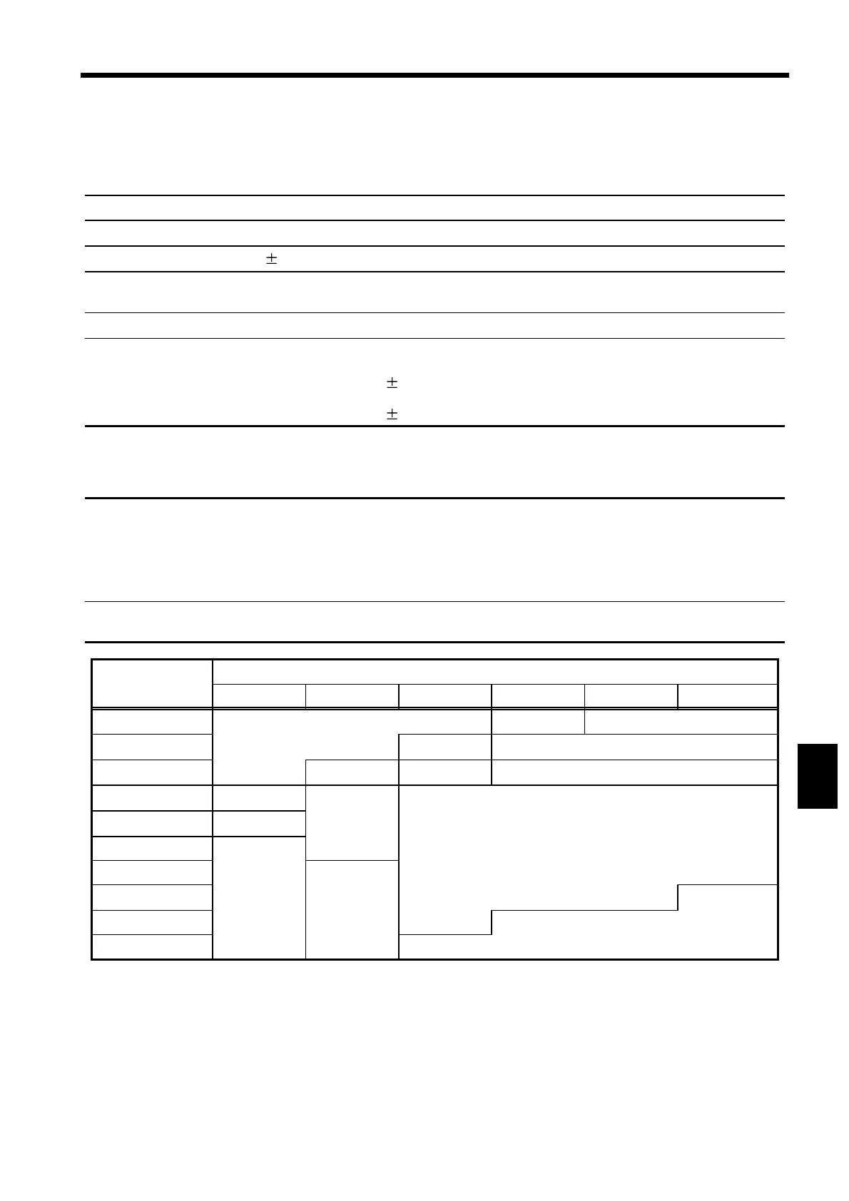
Accuracy See the following table.
(The error limit is added when the scanner is used.)
Resistance
Rm (MΩ)
Test voltage Vt (V)
50
≦
Vt
<
100 100
≦
Vt
<
250 250
≦
Vt
<
500 500
≦
Vt
<
750 750
≦
Vt
<
1000 1000
≦
Vt
≦
1200
5000
<
Rm
≦
9999
Out-of-spec
error limit
25%rdg. 20%rdg.
3000
<
Rm
≦
5000
15%rdg. 10%rdg.
1100
<
Rm
≦
3000
15%rdg. 10%rdg. 5%rdg.
900
<
Rm
≦
1100
20%rdg. 10%rdg. 4%rdg.
100
<
Rm
≦
900
15%rdg.
10.0
<
Rm
≦
100
10%rdg.
1.00
≦
Rm
≦
10.0
5%rdg.
0.500
≦
Rm<1.00
0.250
≦
Rm<0.500
Out of measurement range
0.100
≦
Rm<0.250
Test Voltage
Resistance Measurement
* For resistances Rm listed above that are connected in parallel to
capacitances, accuracy is derived by referring to the JIS C1302 standard.
 Loading...


