34
_____________________________________________________________________________________________
3.4 Starting a Test
______________________________________________________________________________________________
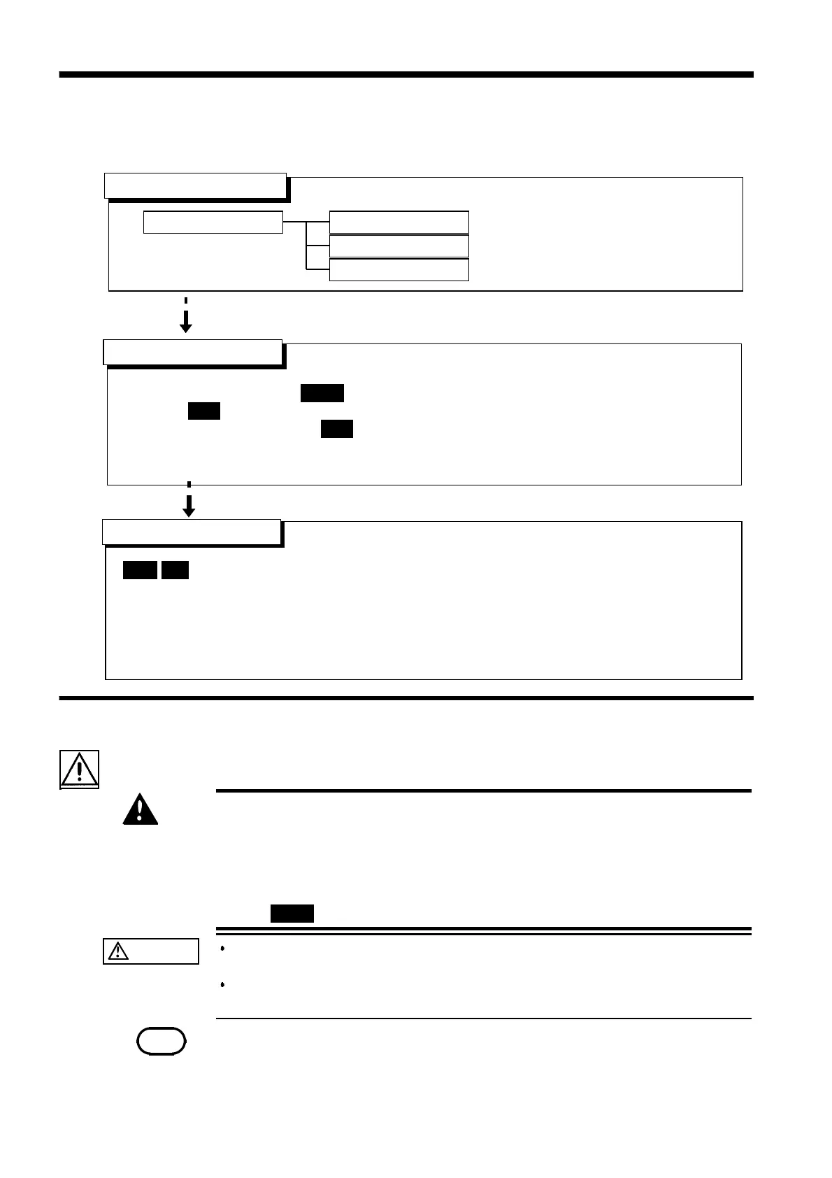
「
READY
状態」での設定
「
READY
状態」での設定
"SETTING" State
Key-lock Function
Optional Function
「
READY
状態」での設定
Starting a Test
Press the
START
key when
READY
is lit. The unit will change to the TEST status and a test
will start.
TEST
and the
DANGER
lamp are lit in the TEST state.
・While the ramp timer is set,
TEST
flashes.
・If the output voltage doesn't reach the set test voltage value ± 5%, the test time timer will
not start (after the ramp-up time has elapsed when the ramp-up time has been set).
PASS
/
FAIL
screening is conducted based on whether a measured-current value exceeds the
upper- or lower-limit value.
If the output voltage fails to reach ±5% of the test voltage within approximately 5 seconds
after the
START
key is pressed (or after the ramp-up time has elapsed, if the ramp-up time
has been set), the unit returns a FAIL result.
・For screening in the ramp timer, see 3.3.4 and 7.12.
See Section 3.3
See Section 3.2.1
See Cha
ter 7
See Section 3.4.1
See Section 3.5
READY state
Setting the test parameters
Determination
3.4.1 Executing a Test
DANGER
To avoid electric shock, observe the following precautions to avoid
electric shock.
Make sure that no high voltage is being applied to the output, confirm
the following items, and output voltage.
(1) The analog voltmeter reads 0 kV.
(2) The
DANGER
lamp is OFF.
(3) The
READY
lamp is lit (it is off in the Double Action mode).
CAUTION
If a capacity load is applied to the tested object, the output voltage may
exceed the preset voltage, thereby damaging the equipment.
Continuous output of a high voltage may heat the bottom of the unit. Take
special care when handling the unit (e.g. transporting the unit).
NOTE
Priority for control of the
START
key is in the following order: the
START
key on the
REMOTE CONTROL BOX, the external I/O, and the front panel of the unit.
Connecting the switch signal line plug on the REMOTE CONTROL BOX disables the
START
ke
on the front
anel of the unit and the start si
nal for the external I/O.
3.4 Starting a Test
The flowchart below explains how a test is carried out.