147
_____________________________________________________________________________________________
9.1 External I/O Terminal
______________________________________________________________________________________________
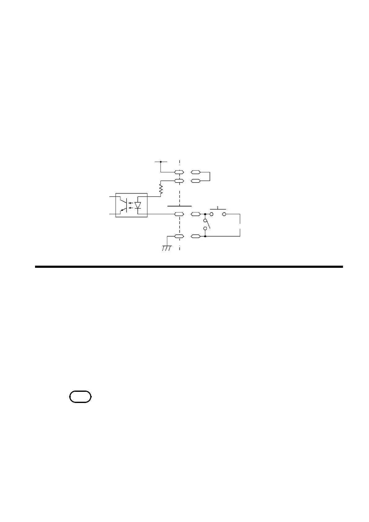
4.7 kΩ
+5 V
Settin
ad
ustment switch
Door switch
Photocou
ler
3153
EXT.DCV
INT.LOCK
ISO.GND
ISO.DCV
ISO.GND
9.1.5 Selecting a Program Test File
NOTE
Do not load files via the external I/O during a file operation such as by operating
the keys or communicating via RS-232C.
(3) Connections for the inter-lock function
For example, to ensure the safety of workers, the unit and the tested object
are placed in a box so that they are not in contact with each other. The door
of the box cover is also equipped with a switch that works in combination
with the inter-lock function. If a connection is made to the switch, the inter-
lock function is enabled when the box cover is opened. When the cover is
closed, the function is disabled, making the unit ready for testing.
All keys are inactive provided that the inter-lock function is active. As a
result, once the unit is mounted in the box, the settings cannot be changed.
In such a case, connect the setting adjustment switch the door switch such
that these switches are arranged in parallel, as shown below:
By setting the test mode of this unit to program mode in advance, through
the
FILE-E
――――――――――
and
FILE-0 to 4
―――――――――――――――
terminals of the external I/O terminal, program
test files can be selected.
1. Connect the
EXT.E
――――――――――
(pin 7) of the external I/O terminal to the ISO GND
(pins 15 and 16). In addition, connect EXT.DCV and ISO.DCV.
2. Select a file by combining the
FILE-0 to 4
―――――――――――――――
signals (see the "File selection
terminal and file numbers" table).
3. When the
FILE-E
――――――――――
terminal is set to LOW level in the program-mode
READY state, the file of the number selected in 2. is loaded.