65
_____________________________________________________________________________________________
4.5 "PASS" or "FAIL" Determination
______________________________________________________________________________________________
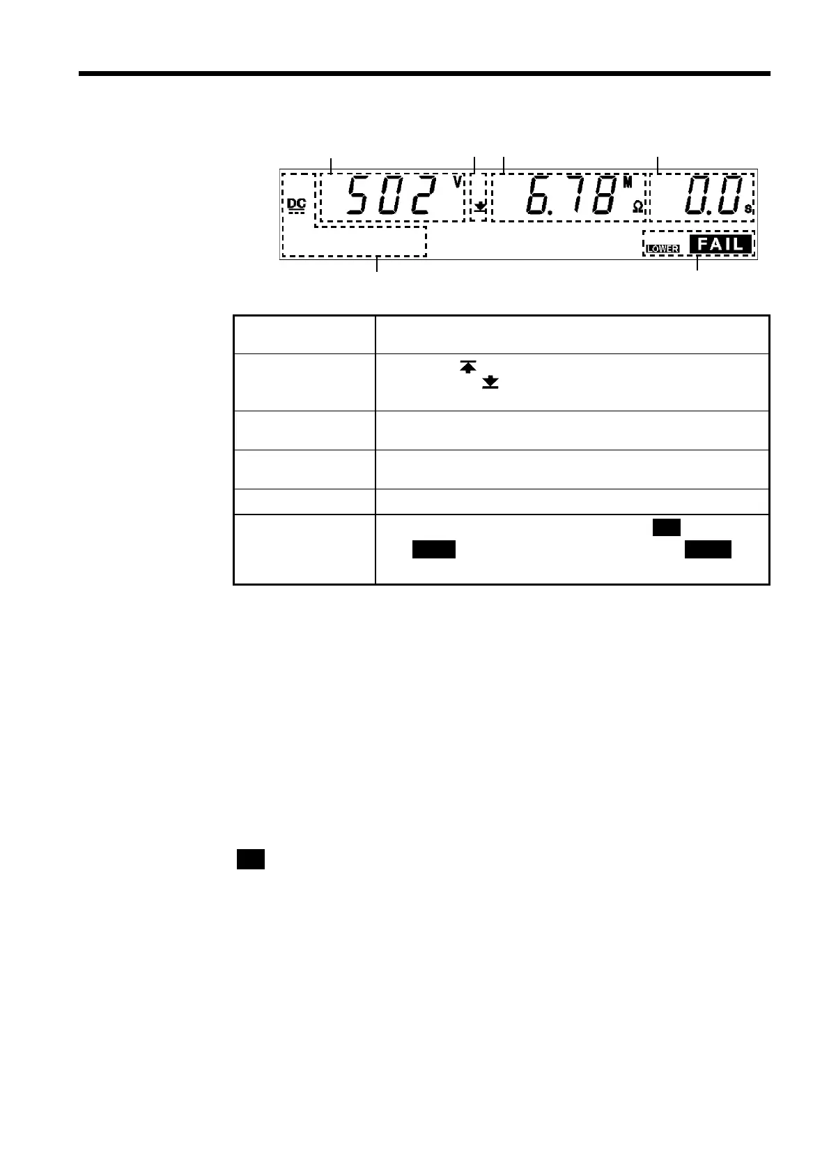
4.5.4 Screening in "FAIL" State
1 2 3
4
5
6
1 Measured
voltage value
Indicates the voltage in the FAIL state.
2 Upper-limit value
icon and Lower-
limit value icon
The symbol appears when the upper-limit value is set,
and the symbol
appears when the lower-limit value is
set.
3 Measured
resistance value
Indicates the measured resistance value in the FAIL state.
4 Test completion
time
"
0.0s
" is displayed.
5 Test-voltage type
Indicates the test type (DC).
6 FAIL
Indicates that the unit is in the FAIL state.
FAIL
lights up
with
UPPER
to indicate UPPER FAIL, and with
LOWER
to
indicate LOWER FAIL.
Danger lamp
Indicates that a voltage is being output. The lamp stays on during the test.
In the insulation-resistance mode, the lamp will also light if a voltage
exceeding the safety voltage (approximately DC 60 V) remains between the
output terminals after the test has been completed.
Analog voltmeter
Indicates the voltage value being output. Even when values are held using
the "FAIL hold function," the value of the analog voltmeter is not held.
External I/O
The
I-FAIL
――――――――――
signal and either the
U-FAIL
――――――――――
or
L-FAIL
――――――――――
signal come on when
FAIL
lights on the fluorescent indicator.
Both the
I-FAIL
――――――――――
and
U-FAIL
――――――――――
signals, as well as the
L-FAIL
――――――――――
signal remain
ON as long as the FAIL state is held. The
I-FAIL
――――――――――
,
U-FAIL
――――――――――
and
L-FAIL
――――――――――
signals are turned OFF when the FAIL light on the fluorescent indicator goes
out.
If voltage remains in the output-voltage terminal following the termination of
a test, the
H.V.ON
――――――――――
signal remains ON. When the
DANGER
lamp goes out,
the
H.V.ON
――――――――――
signal is immediately turned OFF.