64
_____________________________________________________________________________________________
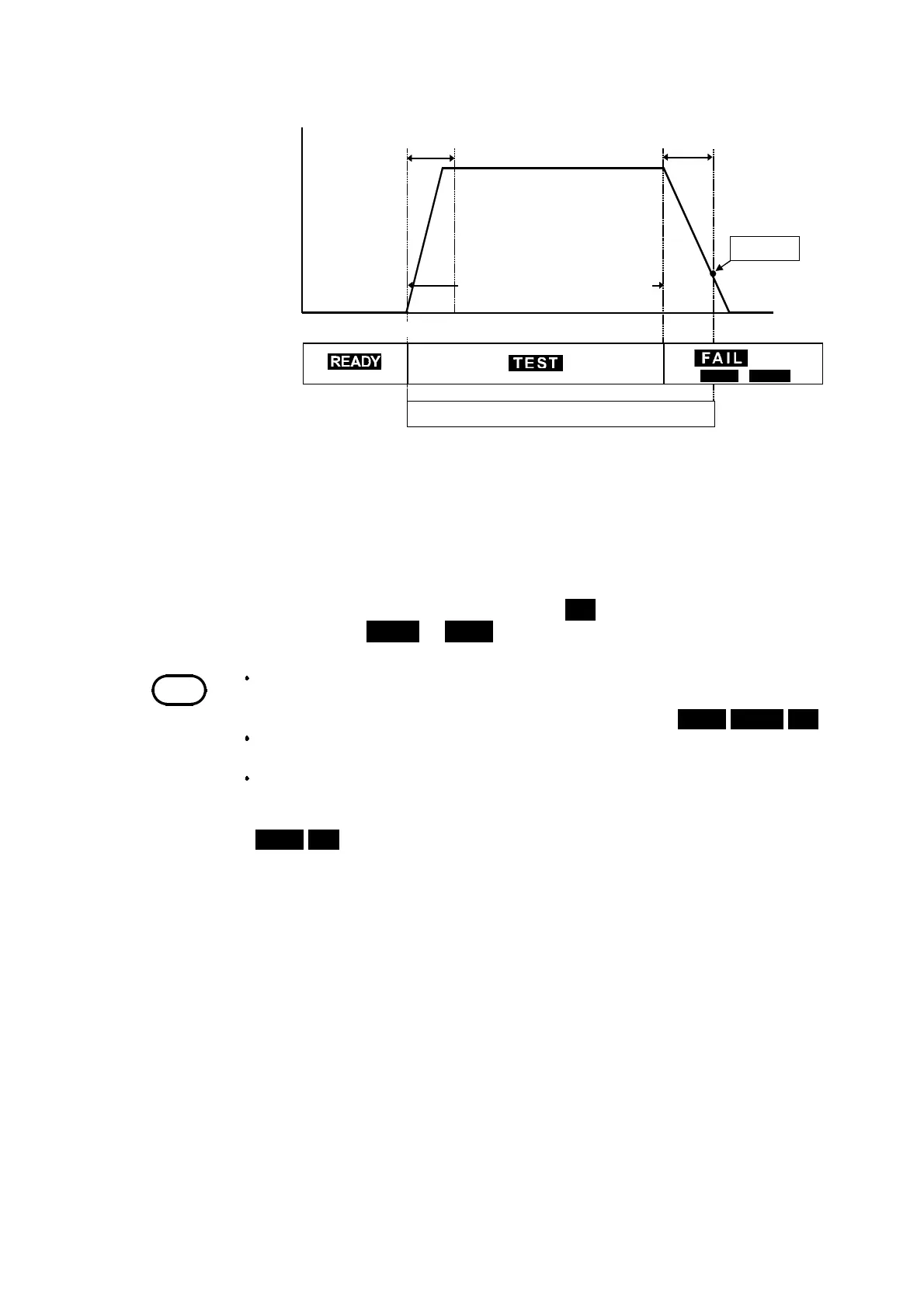
4.5 "PASS" or "FAIL" Determination
______________________________________________________________________________________________
START
DANGER
Lam
UPPER
/
LOWER
Test volta
e
Delay time
Undetermined
eriod
Testin
time when it set u
60 V DC
Electric
dischar
etime
NOTE
When the optional "Insulation Resistance Measurement Range" function is set to
"
1
: Auto Range", it takes up to 1.5 s to display the resistance value. When the
test finishes before the preset test time, the test results in a
UPPER LOWER FAIL
.
When capacitance is present, the time constant based on the capacitance and
resistance values may delay the measurement results.
Setting an upper-limit value while using a fixed range restricts the range of
resistance that can be measured. Therefore, even if a resistance value lower than
the preset upper-limit value is measured, "
O.F.
" is displayed resulting in an
UPPER FAIL
. In addition, even when the measured resistance value is higher than
the preset lower-limit, "
U.F.
" may be displayed, resulting in a LOWER FAIL.
See Section 4.3.2
Flow of FAIL determination
1. Press the
START
key to start a test.
2. A voltage continues to be output until the test time elapses and measure
resistance.
3. When the preset test time has elapsed, and the measured resistance value
deviates from the upper- or lower-limit value, the unit stops outputting a
voltage and switches to the FAIL state.
FAIL
lights up in the FAIL state
together with
LOWER
or
UPPER
.