75
_____________________________________________________________________________________________
5.4 Starting a Test
______________________________________________________________________________________________
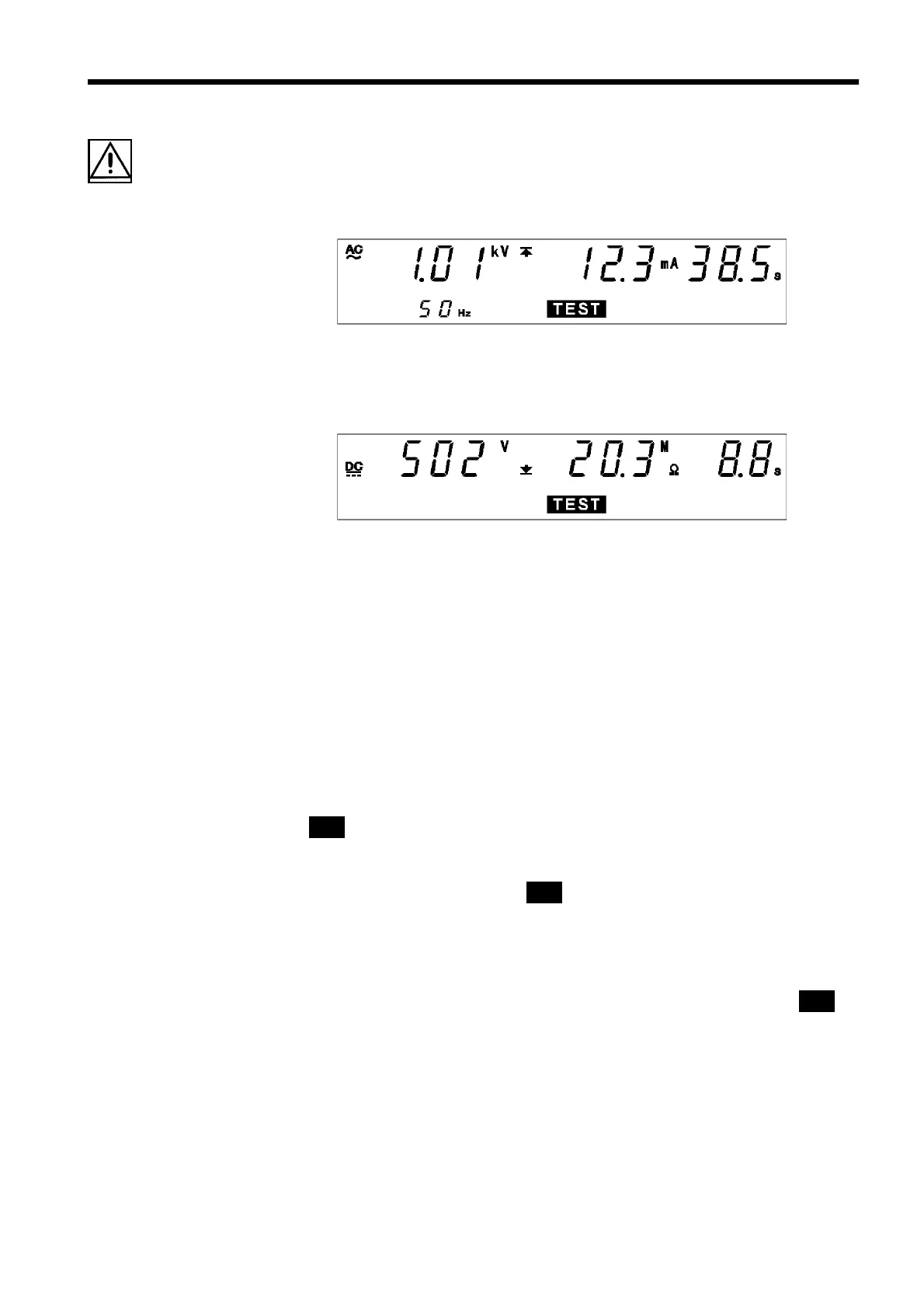
5.4.2 Screening in "TEST" State
(1) When performing a withstand-voltage test:
Similar to the withstand-voltage mode TEST state. (See Section 3.4.2)
(2) When performing an insulation-resistance test:
Similar to the insulation-resistance mode TEST state. (See Section 4.4.2)
Danger lamp
Indicates that a voltage is being output. The lamp stays on during the test.
This lamp remains lit even after completion of the test, if a voltage higher
than the safety voltage (approximately AC 0.03 kV (AC withstand-voltage
test) or approximately DC 60 V (DC withstand-voltage test or insulation-
resistance test) has flowed between output terminals.
Analog voltmeter
Indicates the voltage value being output.
External I/O
The timing when the
TEST
―――――――
signal is turned ON is the same as the timing
when
TEST
on the fluorescent indicator lights up (or flashes). The timing
when the
H.V.ON
――――――――――
signal is turned on is the same as when the
DANGER
lamp
lights up. The two signals are turned OFF at the same time.
Upon startup of the test, although
TEST
flashes until the output voltage
reaches the set test voltage or during the ramp-up time, the
TEST
――――――――
signal is
ON.
Optional Functions
Setting can be performed so that the
TEST
――――――――
signal will be OFF while
TEST
flashes. See Section 7.15.