91
_____________________________________________________________________________________________
6.3 Program Setting State
______________________________________________________________________________________________
6.3.1 Examples of Settings
Test-voltage value: 500 V
Upper-limit value: 100 MΩ
Lower-limit value: OFF
Test time: 5.0 s
Delay time: 0.5 s
Test-voltage value: 1.5 kV
Upper-limit value: 20 mA
Lower-limit value: OFF
Test time: 60.0 s
Ramp-uptime:5.0s
Ramp-down time: OFF
Test-voltage value: 2.0 kV
Upper-limit value: 10 mA
Lower-limit value: OFF
Test time: 3.0 s
Ramp-up time: OFF
Ramp-down time: OFF
This is a description of the procedure for making settings for a program test
under the conditions specified below. Create a program for conducting a test
in the following order and under the following conditions:
Step 1. Insulation-resistance test
Step 2. AC-withstand-voltage test (50 Hz)
Step 3. DC-withstand-voltage test
・
Create a program in file No. 2.
・
The scanner is not used.
The unit should be in the program-mode READY state.
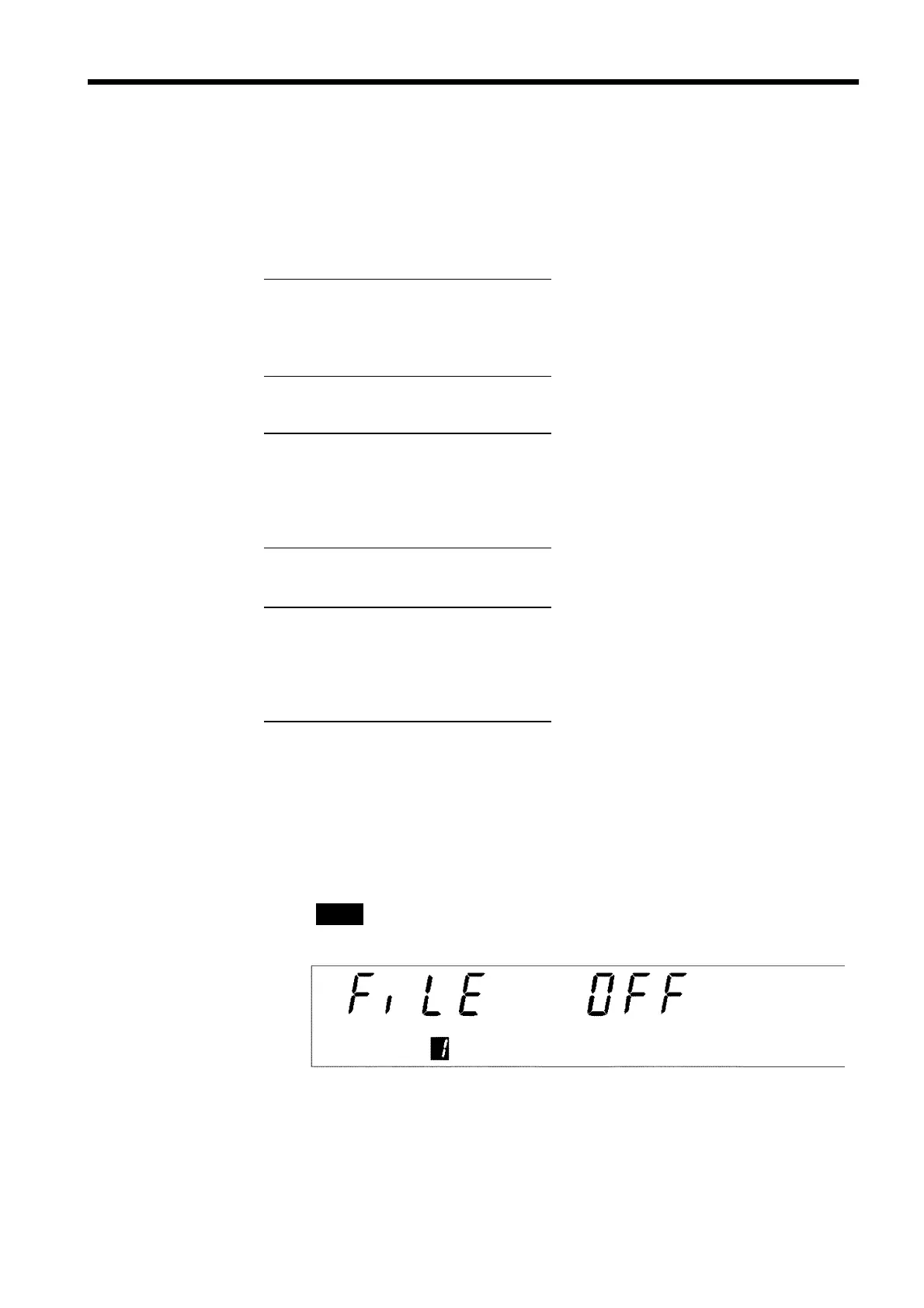
(1) Move to the program setting state.
When the
ENTER
key is pressed, the unit changes to the "program setting
state."
READY
goes off and the file-number setting window is displayed (the
FILE No.
lamp lights up).