3
_____________________________________________________________________________________________
1.2 Names and Functions of Parts
______________________________________________________________________________________________
1
2
3
4
5
6
7
8
9
10
11
12
13
14
A
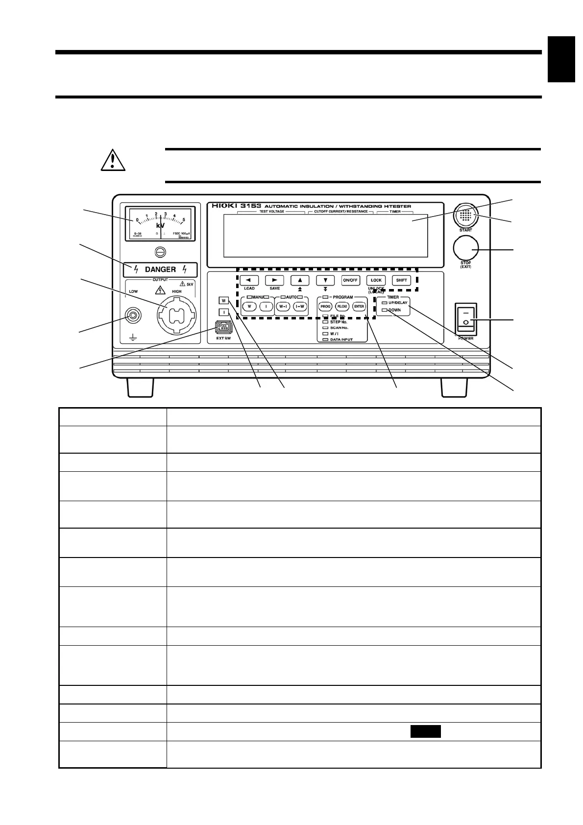
1.2.1 Front panel
WARNING
To prevent electric shock, when the
DANGER
lamp is lit, never touch the
HIGH or LOW terminals, H.V. TEST LEAD, or the tested object.
8
14
13
12
11
1
2
3
4
5
7
6
10
9
1 Analog voltmeter
Indicates output-voltage value.
2
DANGER lamp
This lamp lights to warn that voltage is present between the terminals during
testing.
3 HIGH terminal
The HIGH terminal is a high-voltage terminal for voltage outputs.
4 LOW terminal
The LOW terminal is a low-voltage terminal for voltage outputs. It has the same
electric potential as the unit body.
5 External switch
terminal
Used for the switch signal line plug for the REMOTE CONTROL BOX.
6 I lamp
This lamp lights when insulation-resistance mode is selected and during
insulation-resistance testing.
7 W lamp
This lamp lights when withstand-voltage mode is selected and during withstand-
voltage testing.
8 Rubber keys
The 14 rubber keys include 13 function keys and a
SHIFT
key.
The six function keys offer a variety of settings, used in combination with the
SHIFT
key.
9 DOWN lamp
This lamp lights during ramp-down from withstand-voltage testing.
10 UP/DELAY
lamp
This lamp lights during ramp-up to withstand-voltage testing and during
insulation-resistance testing delays. (However, it does not light during time testing
when insulation-resistance test termination mode is set to 0 [initial setting].)
11 Main power switch
Powers the 3153 product on or off.
12 STOP key
Normally used to terminate a test.
13 START key
Used to start a test. This key functions only when the
READY
lamp is lit.
14 VFD (vacuum
fluorescent display)
Displays various information, such as the test state and test results.
1.2 Names and Functions of Parts