143
_____________________________________________________________________________________________
9.1 External I/O Terminal
______________________________________________________________________________________________
1
2
3
4
5
6
7
8
9
10
11
12
13
14
15
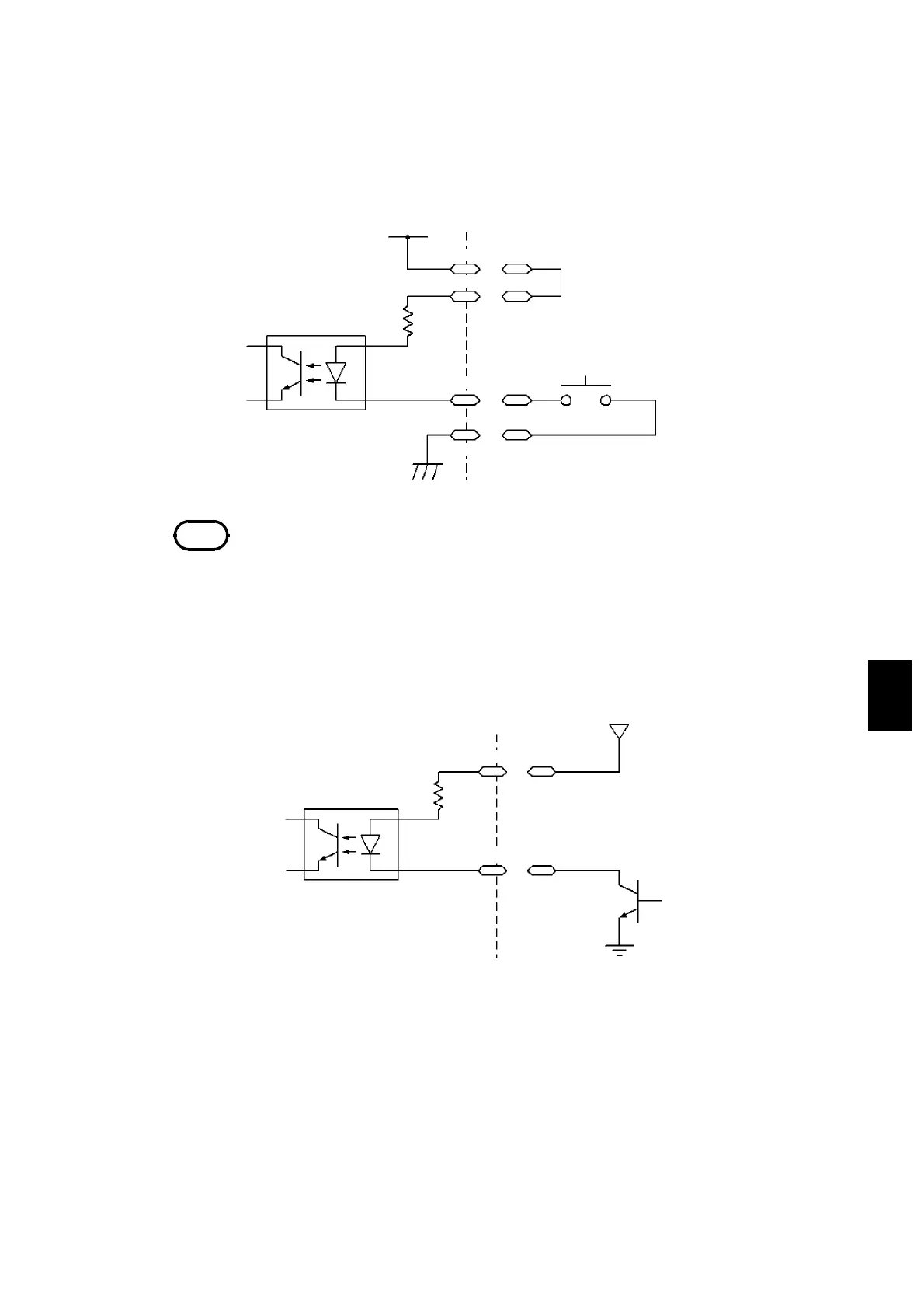
Photocou
ler
+5 V
4.7 kΩ
External Switch
EXT.DCV
External I/O Terminal
ISO.GND
3153
ISO.DCV
NOTE
For connection to the input signal, provide a circuit that protects the relay and
switch from chattering to prevent malfunctioning.
Photocou
ler
EXT.DCV
.7 kΩ
GND of the external
ower su
l
External I/O Terminal
External
ower su
l
3153
(1) Control using the external switch (When the internal power
supply is used)
To control the START and STOP signals using a relay or switch, make
connections as shown below:
(2) Control using the transistor (When the external power supply is
used)
For control using a transistor or FET, make connections as shown below.
Design the signals so that 6 mA is absorbed into each of the signals.