40
_____________________________________________________________________________________________
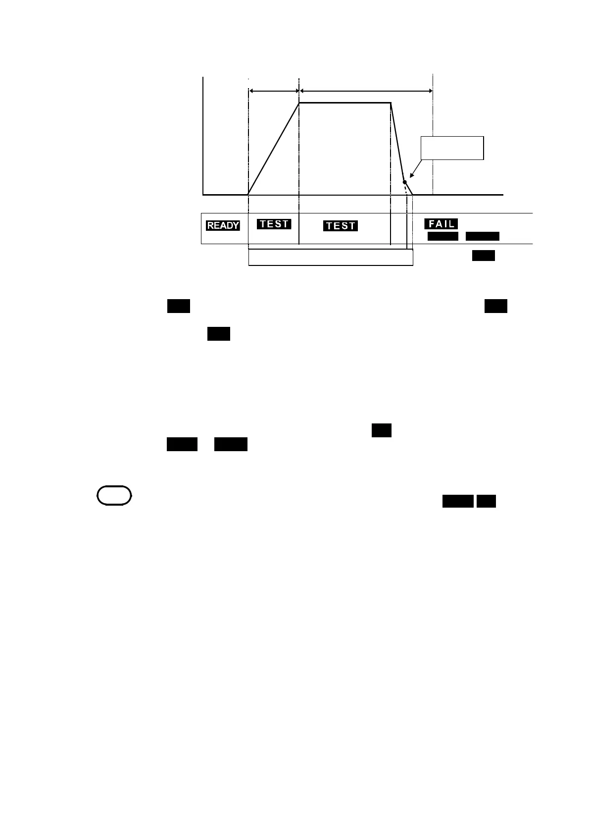
3.5 "PASS" or "FAIL" Determination
______________________________________________________________________________________________
Testin
time when it set u
Flashin
DANGER
Lam
(
UPPER
/
LOWER
)
0.03 kV AC or
0.06 kV DC
Ram
-u
time
*
*
: TEST Flashing
Out
ut volta
e
Time
NOTE
If the current generated is several times as large as the upper-limit value, a circuit
promptly cuts off the high voltage, thereby switching the unit to
UPPER FAIL
.At
this point, an incorrect value for the measured current is displayed.
*Forscreenin
in the ram
timer
see 3.3.4 and 7.12.
Flow of FAIL determination
1. Press the
START
key to start a test.
2.
TEST
flashes until the output voltage reaches the set test voltage.
TEST
also
flashes during the ramp-up time. When the output voltage reaches the test
voltage,
TEST
remains lit, and the reduction timer starts counting down the
test time.
3. A voltage continues to be output until the test time elapses. If the
measured current deviates from the upper- or lower-level value during this
period, the unit switches to the FAIL state.
4. Once a switch is made to the FAIL state,
FAIL
lights up, together with
UPPER
or
LOWER
. The unit stops outputting a voltage and the reduction
timer stops.