466
Hi-Therma Monobloc System (AHZ-044/080HCDS1)
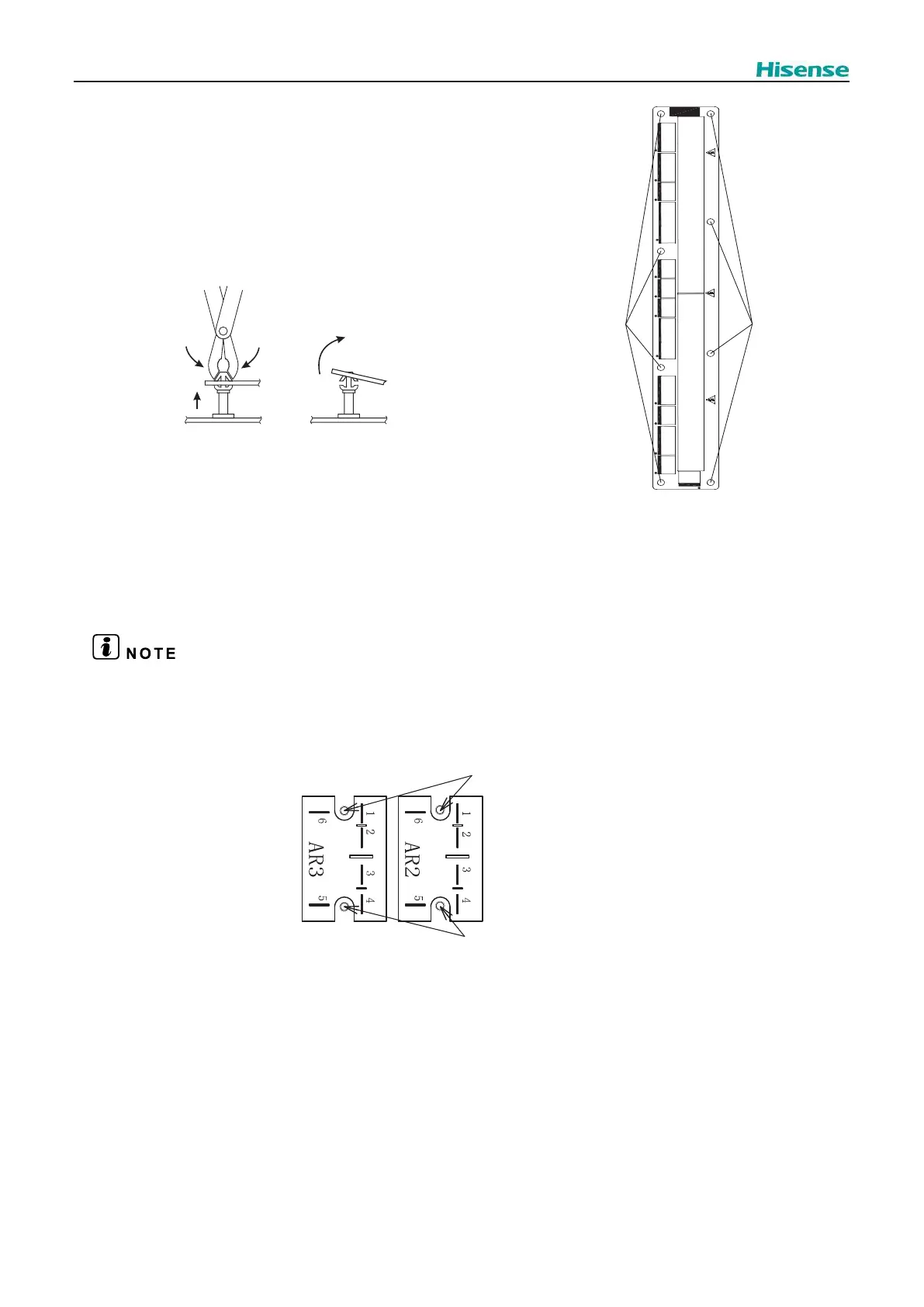
2.4.7.4.5. Removing the PCB5
To Remove the PCB5, the following operations should be done:
Remove the Service cover, as explained in “2.3.1.2 Removing the Service cover”.
Remove the electrical box cover, as explained in “2.3.1.3 Removing the electrical
box cover”,
Then
1. Remove all the connectors connected to the PCB5
2.
Plastic holders (x8)
3. Remove the PCB5. If necessary, replace the PCB5
with a new one proceeding in reverse way than
disassembling.
Plastic holders
Plastic holders
2.4.7.4.6 Removing the relays (AR2~3)
Remove the service cover as explained in chapter “2.3.1.2 Removing the service cover”
Remove the Electrical box cover as explained in chapter “2.3.1.3 Removing the Electrical box cover”
Then,
1. Identify the abnormal relay. Once detected, disconnect the cables.
Take note of the connections on the Relays. Check the wiring diagram for any doubt. Any incorrect connection may damage the unit.
2. Remove the screws attaching the relay to the Electrical box.
Screws
Screws