84 H-S81-HS Installation & Operation Manual — P/N LS10114-000HI-E:A 2/24/2015
Parts of the H-S81-HS System I/O modules
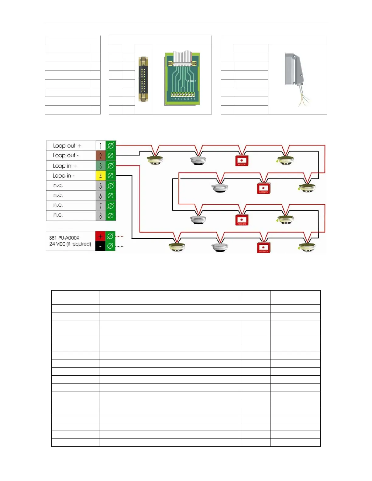
Standard Connection Diagrams
Supported Devices
This module can control the following types of System Sensor addressable devices:
Function Termination with Flat Cable Termination with Multi-conductor Cable
+Loop Output
+ ∅ 1
S81-T8003-1
1
White
S81/CCT4
-Loop Output
- ∅ 22
Brown
+Loop Input
+ ∅ 33
Green
-Loop Input
- ∅ 44
Yellow
---
∅ 55
---
∅ 66
---
∅ 77
---
∅ 88
Figure 2.41 Field Connections
Figure 2.42 Loop standard connection diagram
Part Number Description
Addresses
Used
Type
Pro-S81
CMA1-I Module with 1 output with isolator 1 CON/FORC
M701E Module with 1 output with isolator 1 CON/FORC
MMA1-I Module with 1 input with isolator 1 MON3
M710E Module with 1 input with isolator 1 MON3
M720E Module with 2 inputs with isolator 2 MON3
CMA11 Module with 1 input & 1 output 2 MON3/CON/FORC
M721E Module with 2 inputs & 1 output 3 MON3/FORC
CMA22 Module with 2 inputs & 2 outputs 4 MON3/CON/FORC
CMX-10RM Module with 5 inputs & 5 outputs 10 MON3/FORC
MCX-55M Module with 5 inputs & 5 outputs 10 MON3/FORC
MMX-10M Module with 10 inputs 10 MON3
CMX-10RM Module with 10 relay outputs 10 FORC
M710ECZ Module with 1 input for conventional detectors 1 SCON
M710ECZR Module with 1 input for conventional EExd detectors 1 SCON
MMT Module for 4-20mA analog interface with 1 channel 1 TEC2
IIG4N Module for 4-20mA analog interface with 4 channels 4 TEC2
M700KW Outdoor red alarm button with isolator 1 PULL
M700KI Red alarm button with isolator 1 PULL
 Loading...


