Node 7
Log (log ampliiier output detector)
Perform step
A3
to set up a power sweep on the analog bus. Then press
LMeas)
.::::
.:..
:,:::
:::,::::::,::.,..::,~~
,.
‘;:~~p;$~~:
p’
:~~~~.~.~~~~~
@
(XJ
@izzTq
~~~~~~~~~:.
:~~.~;;:.:.:.~~~.:.~.:,..~
_i
iii
.,.,.,.,.,...,...,....,.,
._
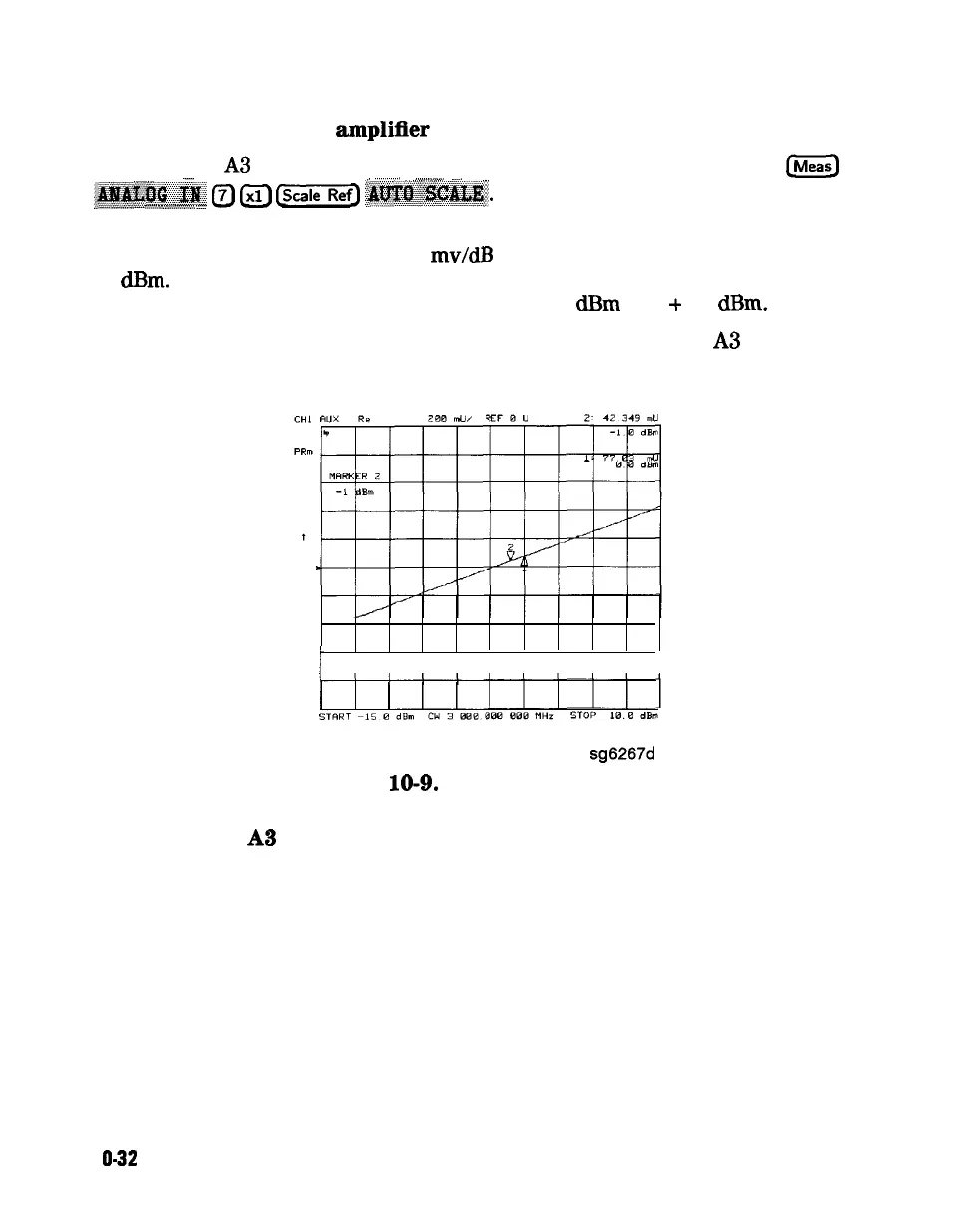
Node 7 displays the output of a logger circuit in the ALC loop. The trace should
be a linear ramp with a slope of 33 mv/dB with approximately 0 volts at
-3
dBm.
Absolute voltage level variations are normal. Flat segments indicate
ALC saturation and should not occur between -15
dBm
and
+
10
deem.
The proper waveform at node 7 indicates that the circuits in the A3 source ALC
loop are normal and the source is leveled.
t
i i i i i i i i i 1
sg6267d
Figure
10-9.
Analog Bus Node 7
Node 8
A3 Gnd (ground)
1 O-32
Service Key Menus and Error Messages